APPENDIX A
LD100/LD100U Remote Control Operation
Overview
Remote control of the LD100 / LD100U Line Doubler is provided by an
Communication Settings
Communication with the LD100 Line Doubler is accomplished by setting the following conditions: 9600, No Parity, 8 Data Bits and 1 Stop Bit. The fac- tory BUAD rate is set at 9600, but rates of 1200, 2400 and 4800 are also available.
Baud Rate Selection
To change the
DIP Switch Settings
Rate | 1 | 2 | 3 | 4 |
|
|
|
|
|
1200 | ON | ON | ON | ON |
|
|
|
|
|
2400 | OFF | ON | ON | ON |
|
|
|
|
|
4800 | ON | OFF | ON | ON |
|
|
|
|
|
*9600 | OFF | OFF | ON | ON |
|
|
|
|
|
* = Factory Preset
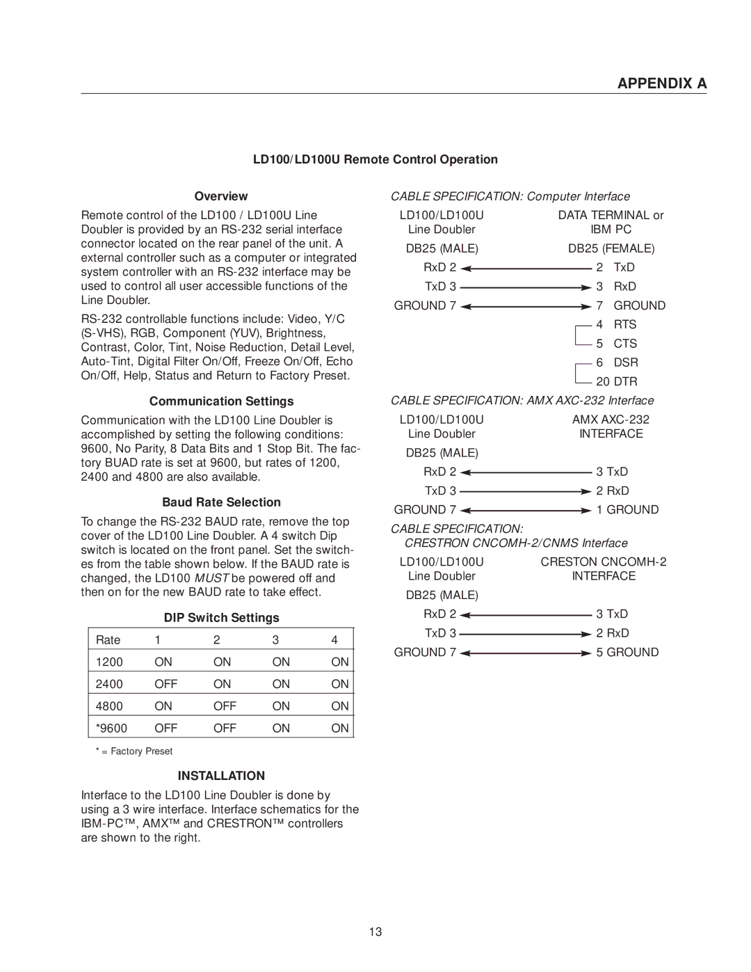
INSTALLATION
CABLE SPECIFICATION: Computer Interface
LD100/LD100U | DATA TERMINAL or | |||||||
Line Doubler |
|
| IBM PC | |||||
DB25 (MALE) | DB25 (FEMALE) | |||||||
RxD 2 |
|
|
|
| 20 TxD | |||
|
|
|
| |||||
TxD 3 |
|
|
|
|
| 30 RxD | ||
|
|
|
|
| ||||
GROUND 7 |
|
|
|
| 70 GROUND | |||
|
|
|
| |||||
|
|
|
|
|
|
|
| 40 RTS |
|
|
|
|
|
|
|
| |
|
|
|
|
|
|
|
| 50 CTS |
|
|
|
|
|
|
|
| |
|
|
|
|
|
|
|
| 60 DSR |
|
|
|
|
|
|
|
| |
|
|
|
|
|
|
|
| 20 DTR |
|
|
|
|
|
|
|
| |
CABLE SPECIFICATION: AMX | ||||||||
LD100/LD100U | AMX | |||||||
Line Doubler |
| INTERFACE | ||||||
DB25 (MALE) |
|
|
|
| ||||
RxD 2 |
|
|
|
| 3 TxD | |||
|
|
|
| |||||
TxD 3 |
|
|
|
| 2 RxD | |||
|
|
|
| |||||
GROUND 7 |
|
|
|
| 1 GROUND | |||
|
|
|
| |||||
CABLE SPECIFICATION:
CRESTRON CNCOMH-2/CNMS Interface
LD100/LD100U | CRESTON | ||||
Line Doubler | INTERFACE | ||||
DB25 (MALE) |
|
|
| ||
RxD 2 |
|
|
| 3 TxD | |
|
|
| |||
TxD 3 |
|
|
| 2 RxD | |
|
|
| |||
GROUND 7 |
|
|
| 5 GROUND | |
|
|
| |||
Interface to the LD100 Line Doubler is done by using a 3 wire interface. Interface schematics for the
13