LINE DOUBLER OPERATING INSTRUCTIONS
For reasons of clarity, this technical overview has been written specifically for the LD100. This description applies as well to the LD100U, with the following exceptions:
1.The LD100U accepts PAL and NTSC signals and switches automatically to the proper standard.
2.Tint control is not operational with PAL sources.
1 | 2 | 3 | 4 | 5 | 6 | 7 |
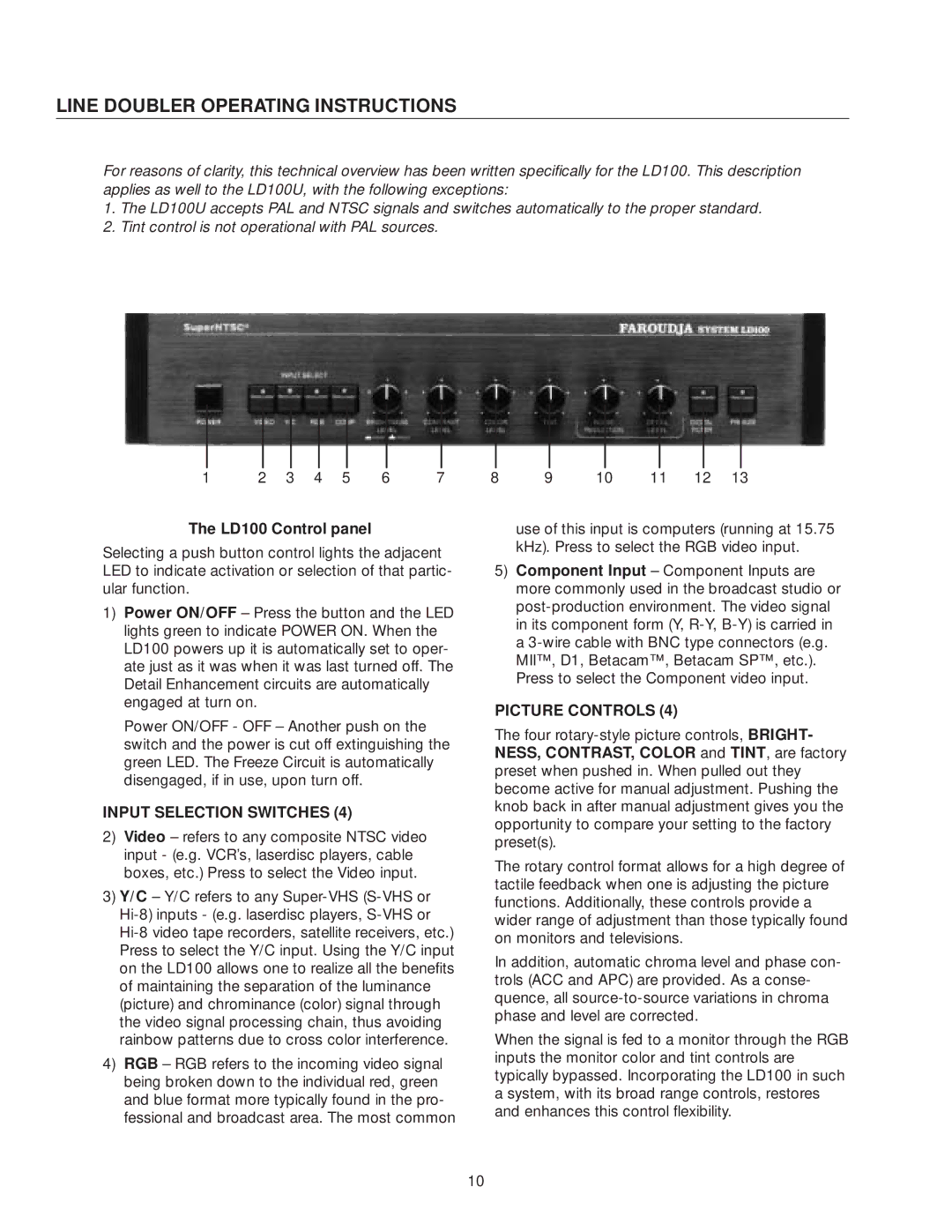
The LD100 Control panel
Selecting a push button control lights the adjacent LED to indicate activation or selection of that partic- ular function.
1)Power ON/OFF – Press the button and the LED lights green to indicate POWER ON. When the LD100 powers up it is automatically set to oper- ate just as it was when it was last turned off. The Detail Enhancement circuits are automatically engaged at turn on.
1)Power ON/OFF - OFF – Another push on the switch and the power is cut off extinguishing the green LED. The Freeze Circuit is automatically disengaged, if in use, upon turn off.
INPUT SELECTION SWITCHES (4)
2)Video – refers to any composite NTSC video input - (e.g. VCR’s, laserdisc players, cable boxes, etc.) Press to select the Video input.
3)Y/C – Y/C refers to any
4)RGB – RGB refers to the incoming video signal being broken down to the individual red, green and blue format more typically found in the pro- fessional and broadcast area. The most common
8 9 10 11 12 13
4)use of this input is computers (running at 15.75 kHz). Press to select the RGB video input.
5)Component Input – Component Inputs are more commonly used in the broadcast studio or
PICTURE CONTROLS (4)
The four
The rotary control format allows for a high degree of tactile feedback when one is adjusting the picture functions. Additionally, these controls provide a wider range of adjustment than those typically found on monitors and televisions.
In addition, automatic chroma level and phase con- trols (ACC and APC) are provided. As a conse- quence, all
When the signal is fed to a monitor through the RGB inputs the monitor color and tint controls are typically bypassed. Incorporating the LD100 in such a system, with its broad range controls, restores and enhances this control flexibility.
10
