APPENDIX B
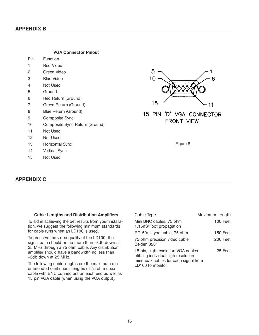
VGA Connector Pinout
Pin Function
1Red Video
2Green Video
3Blue Video
4Not Used
5Ground
6Red Return (Ground)
7Green Return (Ground)
8Blue Return (Ground)
9Composite Sync
10Composite Sync Return (Ground)
11Not Used
12Not Used
13 | Horizontal Sync | Figure 8 |
14Vertical Sync
15Not Used
APPENDIX C
Cable Lengths and Distribution Amplifiers
To aid in achieving the bet results from your installa- tion, we suggest the following minimum standards for cable runs when an LD100 is used.
To preserve the video quality of the LD100, the signal path should be no more than
The following cable lengths are the maximum rec- ommended continuous lengths of 75 ohm coax cable with BNC connectors on each end as well as 15 pin VGA cable (when using the VGA output).
Cable Type | Maximum Length | ||
Mini BNC cables, 75 ohm |
| 100 | Feet |
1.15nS/Foot propagation |
|
|
|
| 150 | Feet | |
75 ohm precision video cable |
| 200 | Feet |
Belden 8281 |
|
|
|
15 pin, high resolution VGA cables | 25 | Feet | |
utilizing individual high resolution |
|
|
|
|
| ||
LD100 to monitor. |
|
|
|
16