SYSTEM DESCRIPTION
Circuit Description
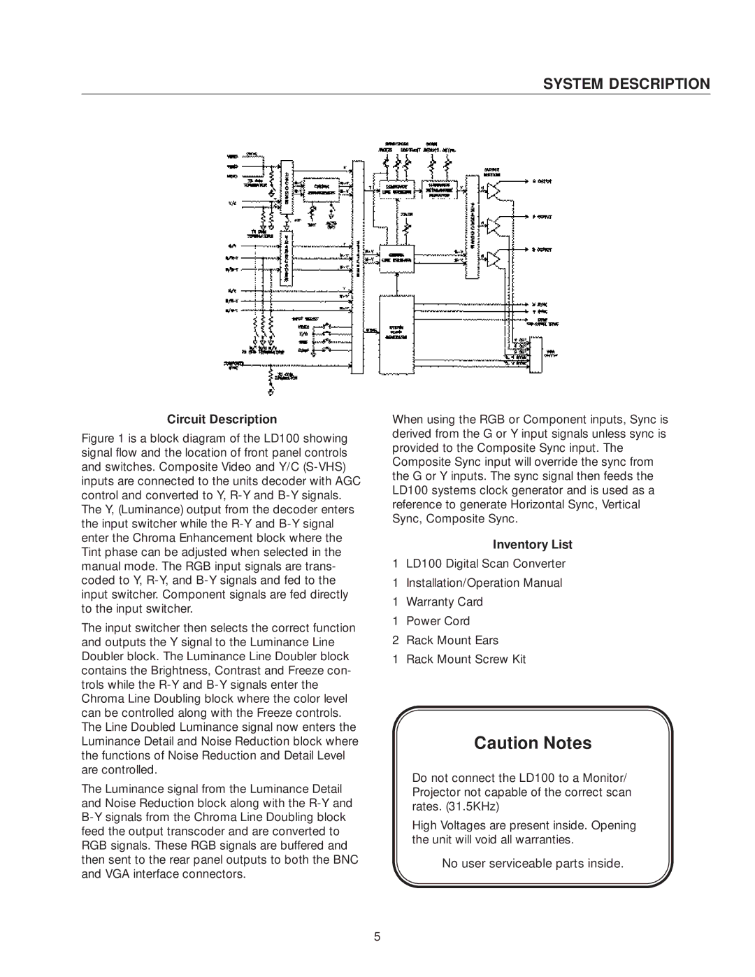
Figure 1 is a block diagram of the LD100 showing signal flow and the location of front panel controls and switches. Composite Video and Y/C (S-VHS) inputs are connected to the units decoder with AGC control and converted to Y, R-Y and B-Y signals. The Y, (Luminance) output from the decoder enters the input switcher while the R-Y and B-Y signal enter the Chroma Enhancement block where the Tint phase can be adjusted when selected in the manual mode. The RGB input signals are trans- coded to Y, R-Y, and B-Y signals and fed to the input switcher. Component signals are fed directly to the input switcher.
The input switcher then selects the correct function and outputs the Y signal to the Luminance Line Doubler block. The Luminance Line Doubler block contains the Brightness, Contrast and Freeze con- trols while the R-Y and B-Y signals enter the Chroma Line Doubling block where the color level can be controlled along with the Freeze controls. The Line Doubled Luminance signal now enters the Luminance Detail and Noise Reduction block where the functions of Noise Reduction and Detail Level are controlled.
The Luminance signal from the Luminance Detail and Noise Reduction block along with the R-Y and B-Y signals from the Chroma Line Doubling block feed the output transcoder and are converted to RGB signals. These RGB signals are buffered and then sent to the rear panel outputs to both the BNC and VGA interface connectors.
When using the RGB or Component inputs, Sync is derived from the G or Y input signals unless sync is provided to the Composite Sync input. The Composite Sync input will override the sync from the G or Y inputs. The sync signal then feeds the LD100 systems clock generator and is used as a reference to generate Horizontal Sync, Vertical Sync, Composite Sync.
Inventory List
1LD100 Digital Scan Converter
1Installation/Operation Manual
1Warranty Card
1Power Cord
2Rack Mount Ears
1 Rack Mount Screw Kit
Caution Notes
Do not connect the LD100 to a Monitor/ Projector not capable of the correct scan rates. (31.5KHz)
High Voltages are present inside. Opening the unit will void all warranties.
No user serviceable parts inside.
5
