•Slide the card in until the top and bottom edges of the front panel are flush and even with the top and bottom edges of the chassis.
•To secure the line card to the chassis, turn the thumbscrew clockwise until it is snug. The card is now properly installed and ready for connection to the network.
•It is not necessary to install a management card in the remote chassis containing an access line card. Management of the remote access line card is provided through the local management card and the fiber link connecting the two access line cards.
4Connect to the Network
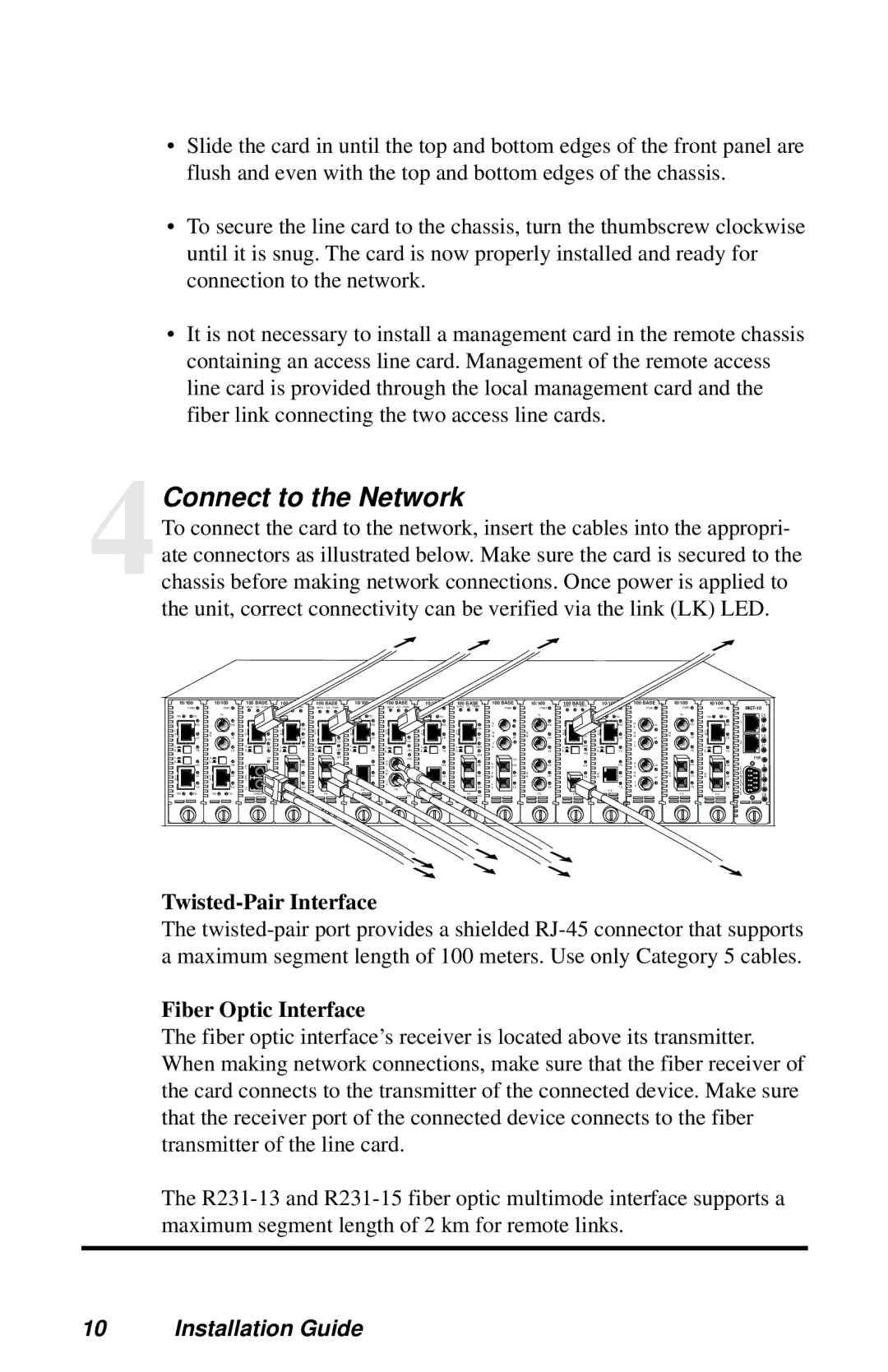
To connect the card to the network, insert the cables into the appropri- ate connectors as illustrated below. Make sure the card is secured to the chassis before making network connections. Once power is applied to the unit, correct connectivity can be verified via the link (LK) LED.
10/100 | 10/100 | 100 BASE | 100 BASE | 100 BASE | 10/100 | 100 BASE | 10/100 | 100 BASE | 100 BASE | 10/100 | 100 BASE | 10/100 | 100 BASE | 10/100 | 10/100 |
PWR | PWR | MAN FD PWR | MAN FD PWR | MAN FD PWR | PWR | MAN FD PWR | PWR | MAN FD PWR | PWR | PWR | MAN FD PWR | PWR | PWR | PWR | PWR |
100 | FD |
| FL |
|
|
|
|
|
|
| 100 | FD |
| FD | 100 | FD |
|
|
|
|
| FL |
|
|
| 100 | FD |
|
|
| FL | 100 | FD |
|
| RX |
| RX |
|
|
|
|
| LK |
|
| RX |
| RX |
| RX |
|
| R |
|
| RX |
|
| RX |
| RX | R | LK |
| RX |
| RX | 1 |
|
|
|
|
| RX |
|
|
|
|
|
|
| RX | X |
|
|
|
|
| X |
|
|
| |||||||||||
|
|
|
|
| RX |
| T |
|
|
|
| T |
|
|
|
|
|
|
|
|
|
|
|
|
|
|
|
|
|
|
| |||
T |
| M |
| T | LK | T |
|
| T |
|
|
| T |
| T |
| M |
| M |
| T |
|
| T |
| M |
| M |
| T |
|
| ||
X | LK | M | LK | X |
| X | LK | X | AT | X |
| LK | X |
| X | LK | X | LK | M | AT | M | LK | X |
| LK | X | LK | M | AT | M | LK | X | LK |
|
|
|
| LBK |
|
| LK |
|
|
| LK |
|
|
|
|
|
|
|
| T |
|
| 2 | ||||||||||||
|
|
|
|
|
|
|
|
|
|
|
|
|
|
|
|
| T |
|
|
|
|
|
|
|
|
|
|
|
|
| ||||
x |
|
|
| x | DIS | x | LBK | x | LBK | x |
|
| x | LBK | x |
| x | LBK | X |
|
|
| x |
| LBK | x |
| X |
|
|
| x |
|
|
II | TX |
| TX | II |
| II |
| II | II |
| TX | II | II | TX | II |
|
|
|
| TX | II |
| DIS | II | TX |
|
|
| TX | II | TX |
| ||
x |
| x |
|
|
|
|
|
| DIS |
|
|
|
|
|
|
|
| DIS |
|
|
|
|
|
|
|
|
|
|
|
|
|
|
| |
|
|
| RX |
|
|
|
|
|
| R | DIS |
|
|
|
|
| LK |
|
|
|
|
|
|
|
|
|
|
|
|
|
| |||
II |
| II |
|
|
|
|
|
|
|
|
|
|
|
|
|
|
| R |
|
|
|
|
|
|
|
| R |
|
|
|
|
|
| |
| RX |
| RX | RX |
|
| RX |
|
|
|
| RX | X |
|
| RX |
| RX | RX |
| RX |
|
| RX |
| RX | LK |
| RX |
| RX |
| ||
|
| LK |
|
| LK |
|
| S |
|
|
| X |
|
|
|
| X |
|
| C | ||||||||||||||
|
|
|
|
|
|
|
|
|
|
|
|
|
|
|
|
|
|
|
|
|
|
|
|
|
|
|
|
|
|
| ||||
|
|
|
|
|
|
|
|
|
| M |
|
| M |
| M |
|
|
| S |
| M |
|
|
|
| M |
| M |
| M |
| M |
| O |
T | LK | T | LK | 1470 |
|
| LK |
|
| M |
| LK |
| AT | M | LK |
| LK | M | LK | M | LK |
|
| LK | M | LK | M | AT | M | LK | M | LK | N |
X |
| X |
| LBK |
|
|
| AT |
|
|
| T |
|
|
|
|
|
|
|
|
|
|
|
|
|
| T |
|
|
|
| S | ||
| TX |
| TX | TX |
|
| LBK |
|
|
|
| TX | X |
|
| TX |
| LBK | XT | TX |
| TX |
|
| LBK |
| TX | X |
|
| TX |
| TX | O |
|
|
|
| DIS |
|
|
|
|
|
| FX |
| FX |
| FX |
|
|
|
|
|
|
|
|
|
| FX |
|
|
|
|
|
| L | |
100 | FD | 100 | FD |
| CWDM |
| FX |
| FX |
|
|
|
| DIS |
|
| FX | DIS |
|
|
| FX |
| FX | DIS |
|
|
|
|
| FX | FX |
| E |
LK
AT
LK
AT
PWR![]()
A
B
R
ER
Twisted-Pair Interface
The
Fiber Optic Interface
The fiber optic interface’s receiver is located above its transmitter. When making network connections, make sure that the fiber receiver of the card connects to the transmitter of the connected device. Make sure that the receiver port of the connected device connects to the fiber transmitter of the line card.
The
10 Installation Guide