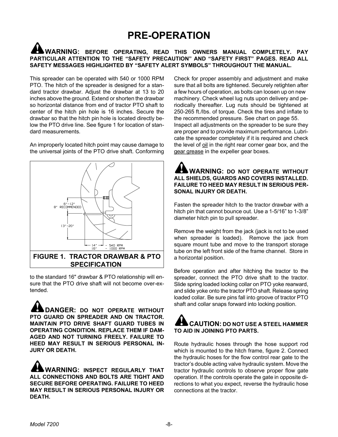
7200 specifications
The Meyer 7200 is a cutting-edge agricultural tractor that stands out in the competitive landscape of modern farming equipment. Designed with efficiency and versatility in mind, it caters to the diverse needs of farmers and agricultural professionals. One of the primary features of the Meyer 7200 is its robust engine, which delivers remarkable power while maintaining fuel efficiency. With a maximum horsepower rating that exceeds expectations, this tractor is capable of handling a wide range of tasks, from plowing and tilling to hauling heavy loads.The Meyer 7200 incorporates advanced technology that enhances its performance and usability. One notable technological feature is the integrated GPS guidance system, which assists farmers in optimizing field operations by providing precise navigation and mapping capabilities. This system not only minimizes overlaps during planting and spraying but also maximizes efficiency and productivity. The tractor is also equipped with an intuitive touchscreen interface, allowing operators to easily monitor performance metrics and adjust settings on-the-go.
Another significant characteristic of the Meyer 7200 is its exceptional maneuverability. The tractor is designed with a compact frame and a superior turning radius, making it adept at navigating tight corners and various terrains. This feature is particularly beneficial in smaller fields or crowded workspaces. Additionally, the tractor boasts an advanced suspension system that enhances ride comfort and stability, reducing operator fatigue during long hours in the field.
Durability is a hallmark of the Meyer 7200, with components built to withstand the rigors of daily farm work. The high-quality materials and robust construction ensure longevity and minimize maintenance requirements. Farmers can rely on the Meyer 7200 to perform reliably under heavy workloads, even in challenging weather conditions.
Safety is also a priority, with features such as roll-over protection structures and advanced braking systems. These safety enhancements provide peace of mind for operators, allowing them to focus on their tasks without added worry.
In summary, the Meyer 7200 is a powerful, efficient, and technologically advanced tractor that meets the demands of modern agriculture. With its powerful engine, integrated GPS system, exceptional maneuverability, durability, and safety features, the Meyer 7200 is an indispensable tool for farmers looking to elevate their productivity and ensure successful harvests. As the agricultural landscape continues to evolve, the Meyer 7200 stands ready to meet the challenges of today and tomorrow.

