Meyer Sound CQ-2 operating instructions Coverage Angles and Polar Plots

Models: CQ-2

1 16
Download 16 pages 58.94 Kb
Page 11
Image 11

Coverage Angles and Polar Plots

Coverage Angles

The coverage angles for the CQ Series over a wide frequency range are summarized in the following table:

CQ Series Coverage Angles


horizontal1

vertical2

CQ-1

(–6 dB points)

80°

40°


CQ-1 (–10 dB points)

100°

50°


CQ-2

(–6 dB points)

50°

40°


CQ-2 (–10 dB points)

60°

50°


The table below lists the maximum on-axis peak dB SPL per octave measured at 1 m for the CQ-1 and CQ-2.

Maximum Peak dB SPL

Frequency

CQ-1

CQ-2


125 Hz

127

127


250 Hz

130

130


500 Hz

130

130


1 kHz

132

139


2 kHz

136

139


4 kHz

136

139


8 kHz

132

134


16 kHz

122

124


1.CQ-1: 500 Hz–16 kHz; CQ-2: 800 Hz–12 kHz

2.CQ-1 and CQ-2: 1.5–12 kHz

The –6 dB points denote the angle at which the measured SPL has decreased to half its on-axis value. The –10 dB points represent the angle at which the perceived SPL has decreased to half its on-axis value.

Polar Plots

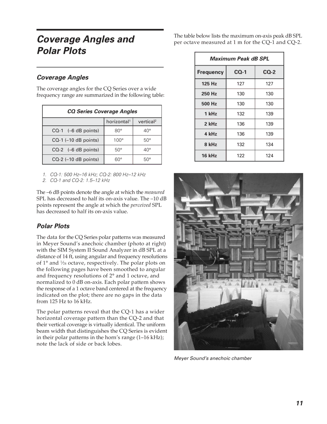
The data for the CQ Series polar patterns was measured in Meyer Sound’s anechoic chamber (photo at right) with the SIM System II Sound Analyzer in dB SPL at a distance of 14 ft, using angular and frequency resolutions of 1° and 124 octave, respectively. The polar plots on the following pages have been smoothed to angular and frequency resolutions of 2° and 1 octave, and normalized to 0 dB on-axis. Each polar pattern shows the response of a 1 octave band centered at the frequency indicated on the plot; there are no gaps in the data from 125 Hz to 16 kHz.

The polar patterns reveal that the CQ-1 has a wider horizontal coverage pattern than the CQ-2 and that their vertical coverage is virtually identical. The uniform beam width that distinguishes the CQ Series is evident in their polar patterns in the horn’s range (1–16 kHz); note the lack of side or back lobes.

Meyer Sound’s anechoic chamber

11

Page 11
Image 11
Meyer Sound CQ-2 operating instructions Coverage Angles and Polar Plots