Complete Systems
Speaker Placement and Polarity
The cabinets in the following example configurations are in a
In a coplanar orientation, externally amplified Meyer subwoofers require the opposite polarity setting to all Meyer
We recommend using the Meyer SIM® System II Sound Analyzer and
• assist the process of configuring and placing |
speakers in a system; |
• measure propagation delays to set the correct |
polarity between speakers; |
• measure and equalize variations in frequency |
response caused by the acoustical environment |
Meyer Speaker Types
The following Meyer speakers will be mentioned in the example applications.
650-R2, MSW-2,
The
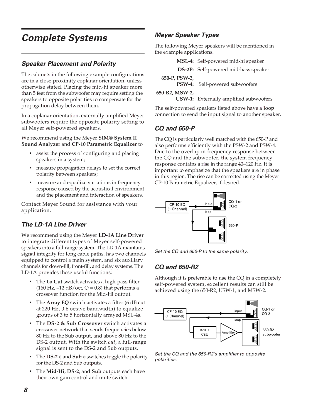
CQ and 650-P
The CQ is particularly well matched with the
and the placement and interaction of speakers. |
Contact Meyer Sound for assistance with your application.
The LD-1A Line Driver
We recommend using the Meyer
(1 Channel)
input | ||
| ||
loop |
| |
|
signal integrity for long cable paths, has two channels equipped to control a main system, and six auxiliary channels for
•The Lo Cut switch activates a
•The Array EQ switch activates a filter (6 dB cut at 220 Hz, 0.6 octave bandwidth) to equalize groups of 3 to 5 horizontally arrayed
•The
•The
•The
Set the CQ and
CQ and 650-R2
Although it is preferable to use the CQ in a completely
input | |||
(1 Channel) |
| ||
loop |
| ||
|
| ||
Amplifier | |||
CEU | subwoofer | ||
|
Set the CQ and the
8