Array Design
Creating an effective array with the CQ requires a precise understanding of how to combine the coverage area and SPL of the individual speaker with those of adjacent speakers. Array design is a
As the splay angle (the angle between adjacent cabinet faces) decreases below the coverage angle of the individual speaker, the
As the splay angle increases toward the coverage angle, the
NOTE: The trapezoidal shape of the CQ does not represent the horizontal coverage area of the speaker or the intended splay angle for horizontal arrays. The 20° angle of the CQ enclosure is narrower than the minimum recommended splay angle.
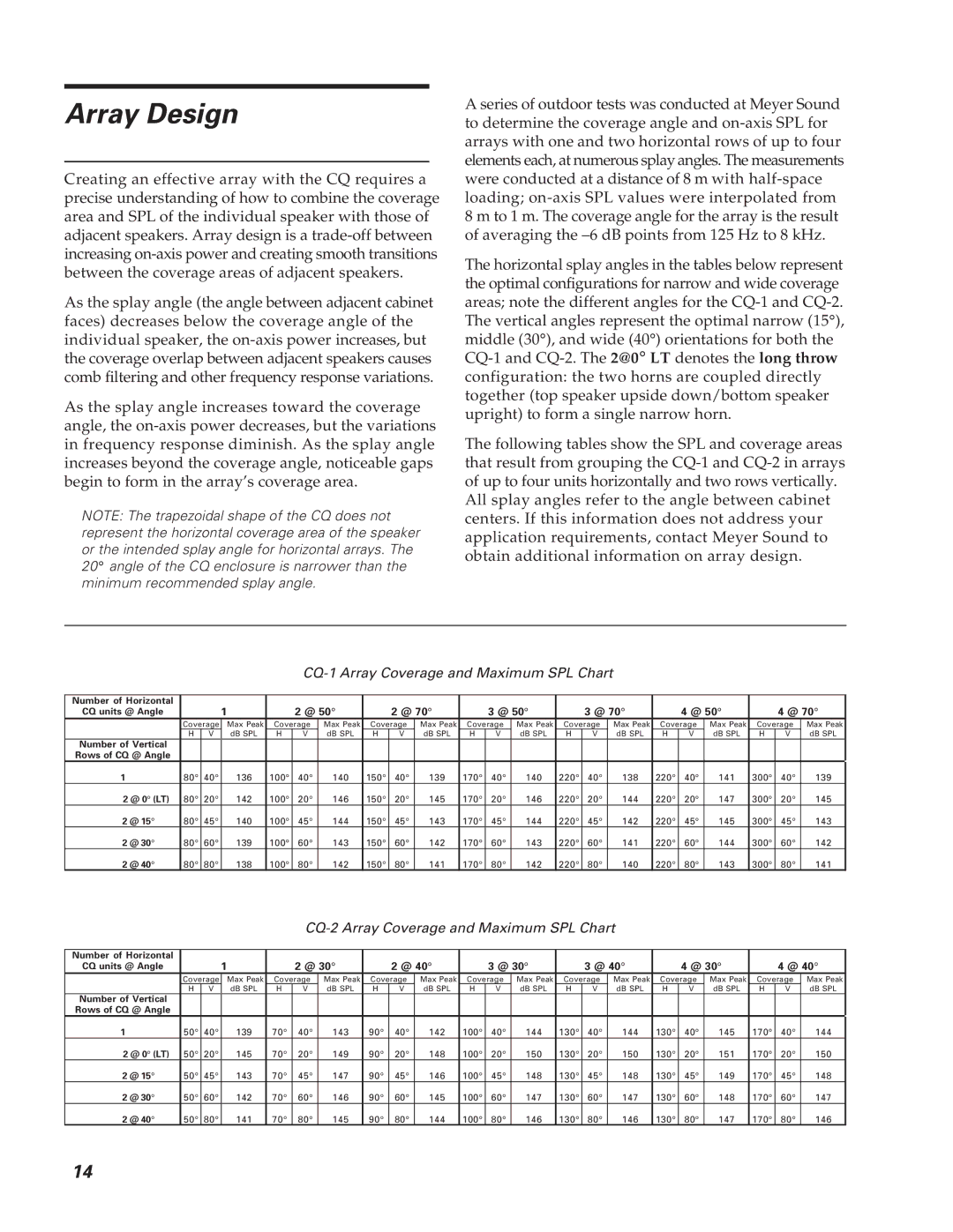
A series of outdoor tests was conducted at Meyer Sound to determine the coverage angle and
The horizontal splay angles in the tables below represent the optimal configurations for narrow and wide coverage areas; note the different angles for the
The following tables show the SPL and coverage areas that result from grouping the
CQ-1 Array Coverage and Maximum SPL Chart
Number of Horizontal |
|
| 1 |
| 2 @ 50° |
| 2 @ 70° |
| 3 @ 50° |
| 3 @ 70° |
| 4 @ 50° |
| 4 @ 70° | ||||||
CQ units @ Angle |
|
|
|
|
|
|
|
| |||||||||||||
| Coverage | Max Peak | Coverage | Max Peak | Coverage | Max Peak | Coverage | Max Peak | Coverage | Max Peak | Coverage | Max Peak | Coverage | Max Peak | |||||||
| H | V | dB SPL | H | V | dB SPL | H | V | dB SPL | H | V | dB SPL | H | V | dB SPL | H | V | dB SPL | H | V | dB SPL |
Number of Vertical |
|
|
|
|
|
|
|
|
|
|
|
|
|
|
|
|
|
|
|
|
|
Rows of CQ @ Angle |
|
|
|
|
|
|
|
|
|
|
|
|
|
|
|
|
|
|
|
|
|
1 | 80° | 40° | 136 | 100° | 40° | 140 | 150° | 40° | 139 | 170° | 40° | 140 | 220° | 40° | 138 | 220° | 40° | 141 | 300° | 40° | 139 |
2 @ 0° (LT) | 80° | 20° | 142 | 100° | 20° | 146 | 150° | 20° | 145 | 170° | 20° | 146 | 220° | 20° | 144 | 220° | 20° | 147 | 300° | 20° | 145 |
2 @ 15° | 80° | 45° | 140 | 100° | 45° | 144 | 150° | 45° | 143 | 170° | 45° | 144 | 220° | 45° | 142 | 220° | 45° | 145 | 300° | 45° | 143 |
2 @ 30° | 80° | 60° | 139 | 100° | 60° | 143 | 150° | 60° | 142 | 170° | 60° | 143 | 220° | 60° | 141 | 220° | 60° | 144 | 300° | 60° | 142 |
2 @ 40° | 80° | 80° | 138 | 100° | 80° | 142 | 150° | 80° | 141 | 170° | 80° | 142 | 220° | 80° | 140 | 220° | 80° | 143 | 300° | 80° | 141 |
CQ-2 Array Coverage and Maximum SPL Chart
Number of Horizontal |
|
| 1 |
| 2 @ 30° |
| 2 @ 40° |
| 3 @ 30° |
| 3 @ 40° |
| 4 @ 30° |
| 4 @ 40° | ||||||
CQ units @ Angle |
|
|
|
|
|
|
|
| |||||||||||||
| Coverage | Max Peak | Coverage | Max Peak | Coverage | Max Peak | Coverage | Max Peak | Coverage | Max Peak | Coverage | Max Peak | Coverage | Max Peak | |||||||
| H | V | dB SPL | H | V | dB SPL | H | V | dB SPL | H | V | dB SPL | H | V | dB SPL | H | V | dB SPL | H | V | dB SPL |
Number of Vertical |
|
|
|
|
|
|
|
|
|
|
|
|
|
|
|
|
|
|
|
|
|
Rows of CQ @ Angle |
|
|
|
|
|
|
|
|
|
|
|
|
|
|
|
|
|
|
|
|
|
1 | 50° | 40° | 139 | 70° | 40° | 143 | 90° | 40° | 142 | 100° | 40° | 144 | 130° | 40° | 144 | 130° | 40° | 145 | 170° | 40° | 144 |
2 @ 0° (LT) | 50° | 20° | 145 | 70° | 20° | 149 | 90° | 20° | 148 | 100° | 20° | 150 | 130° | 20° | 150 | 130° | 20° | 151 | 170° | 20° | 150 |
2 @ 15° | 50° | 45° | 143 | 70° | 45° | 147 | 90° | 45° | 146 | 100° | 45° | 148 | 130° | 45° | 148 | 130° | 45° | 149 | 170° | 45° | 148 |
2 @ 30° | 50° | 60° | 142 | 70° | 60° | 146 | 90° | 60° | 145 | 100° | 60° | 147 | 130° | 60° | 147 | 130° | 60° | 148 | 170° | 60° | 147 |
2 @ 40° | 50° | 80° | 141 | 70° | 80° | 145 | 90° | 80° | 144 | 100° | 80° | 146 | 130° | 80° | 146 | 130° | 80° | 147 | 170° | 80° | 146 |
14