Circulation Pump Wiring Diagrams
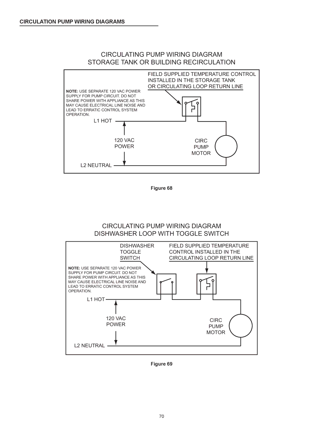
CIRCULATING PUMP WIRING DIAGRAM
STORAGE TANK OR BUILDING RECIRCULATION
FIELD SUPPLIED TEMPERATURE CONTROL
INSTALLED IN THE STORAGE TANK
OR CIRCULATING LOOP RETURN LINE
NOTE: USE SEPARATE 120 VAC POWER
SUPPLY FOR PUMP CIRCUIT. DO NOT
SHARE POWER WITH APPLIANCE AS THIS
MAY CAUSE ELECTRICAL LINE NOISE AND
LEAD TO ERRATIC CONTROL SYSTEM
OPERATION.
L1 HOT
120 VAC | CIRC |
POWER | PUMP |
| MOTOR |
L2 NEUTRAL
Figure 68
CIRCULATING PUMP WIRING DIAGRAM
DISHWASHER LOOP WITH TOGGLE SWITCH
DISHWASHER
TOGGLE
SWITCH
NOTE: USE SEPARATE 120 VAC POWER SUPPLY FOR PUMP CIRCUIT. DO NOT SHARE POWER WITH APPLIANCE AS THIS MAY CAUSE ELECTRICAL LINE NOISE AND LEAD TO ERRATIC CONTROL SYSTEM OPERATION.
L1 HOT
120VAC POWER
L2 NEUTRAL
FIELD SUPPLIED TEMPERATURE CONTROL INSTALLED IN THE CIRCULATING LOOP RETURN LINE
CIRC
PUMP
MOTOR
Figure 69
70