Lighting The Water Heater
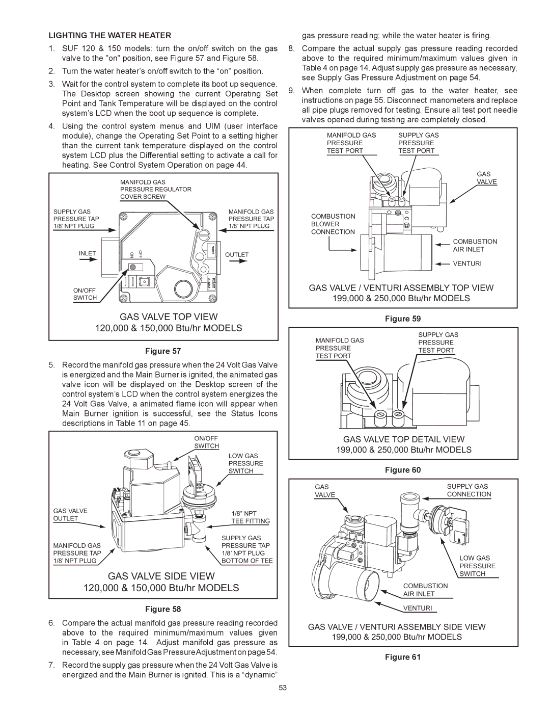
1.SUF 120 & 150 models: turn the on/off switch on the gas valve to the "on" position, see Figure 57 and Figure 58.
2.Turn the water heater’s on/off switch to the “on” position.
3.Wait for the control system to complete its boot up sequence. The Desktop screen showing the current Operating Set Point and Tank Temperature will be displayed on the control system’s LCD when the boot up sequence is complete.
4.Using the control system menus and UIM (user interface module), change the Operating Set Point to a setting higher than the current tank temperature displayed on the control system LCD plus the Differential setting to activate a call for heating. See Control System Operation on page 44.
| MANIFOLD GAS |
|
| PRESSURE REGULATOR |
|
| COVER SCREW |
|
SUPPLY GAS |
| MANIFOLD GAS |
PRESSURE TAP |
| PRESSURE TAP |
1/8’ NPT PLUG |
| 1/8’ NPT PLUG |
INLET | OFF ON | OUTLET |
ON/OFF |
|
|
SWITCH |
|
|
| GAS VALVE TOP VIEW |
|
120,000 & 150,000 Btu/hr MODELS | ||
Figure 57
5.Record the manifold gas pressure when the 24 Volt Gas Valve is energized and the Main Burner is ignited, the animated gas valve icon will be displayed on the Desktop screen of the control system’s LCD when the control system energizes the 24 Volt Gas Valve, a animated flame icon will appear when Main Burner ignition is successful, see the Status Icons descriptions in Table 11 on page 45.
| ON/OFF | |
| SWITCH | |
| LOW GAS | |
| PRESSURE | |
| SWITCH | |
GAS VALVE | 1/8” NPT | |
OUTLET | ||
TEE FITTING | ||
| ||
| SUPPLY GAS | |
MANIFOLD GAS | PRESSURE TAP | |
PRESSURE TAP | 1/8’ NPT PLUG | |
1/8’ NPT PLUG | BOTTOM OF TEE | |
| GAS VALVE SIDE VIEW | |
120,000 & 150,000 Btu/hr MODELS | ||
Figure 58
6.Compare the actual manifold gas pressure reading recorded above to the required minimum/maximum values given in Table 4 on page 14. Adjust manifold gas pressure as necessary, see Manifold Gas PressureAdjustment on page 54.
7.Record the supply gas pressure when the 24 Volt Gas Valve is energized and the Main Burner is ignited. This is a “dynamic”
gas pressure reading; while the water heater is firing.
8.Compare the actual supply gas pressure reading recorded above to the required minimum/maximum values given in Table 4 on page 14. Adjust supply gas pressure as necessary, see Supply Gas Pressure Adjustment on page 54.
9.When complete turn off gas to the water heater, see instructions on page 55. Disconnect manometers and replace all pipe plugs removed for testing. Ensure all test port needle valves opened during testing are completely closed.
MANIFOLD GAS | SUPPLY GAS |
PRESSURE | PRESSURE |
TEST PORT | TEST PORT |
GAS
VALVE
COMBUSTION BLOWER CONNECTION
COMBUSTION AIR INLET
![]() VENTURI
VENTURI
GAS VALVE / VENTURI ASSEMBLY TOP VIEW
199,000 & 250,000 Btu/hr MODELS
| Figure 59 |
MANIFOLD GAS | SUPPLY GAS |
PRESSURE | |
PRESSURE | TEST PORT |
TEST PORT |
|
GAS VALVE TOP DETAIL VIEW
199,000 & 250,000 Btu/hr MODELS
Figure 60
GAS | SUPPLY GAS |
VALVE | CONNECTION |
| LOW GAS |
| PRESSURE |
| SWITCH |
| COMBUSTION |
| AIR INLET |
| VENTURI |
GAS VALVE / VENTURI ASSEMBLY SIDE VIEW | |
199,000 & 250,000 Btu/hr MODELS | |
Figure 61
53