4 | 5 | 6 | 5 | 4 | 13 | 14 |
3 |
|
|
| |||
|
|
|
|
| ||
|
| 2 |
|
|
| |
|
|
|
|
| 3 | |
|
|
| 7 |
|
| |
|
|
|
|
|
| |
2 |
|
| 8 |
|
|
|
|
|
|
|
|
| |
|
|
| 9 |
|
|
|
|
|
|
|
|
| 15 |
|
|
| 10 |
|
|
|
1 |
|
| 11 |
|
|
|
|
|
| 12 |
|
| 16 |
|
|
|
|
|
| |
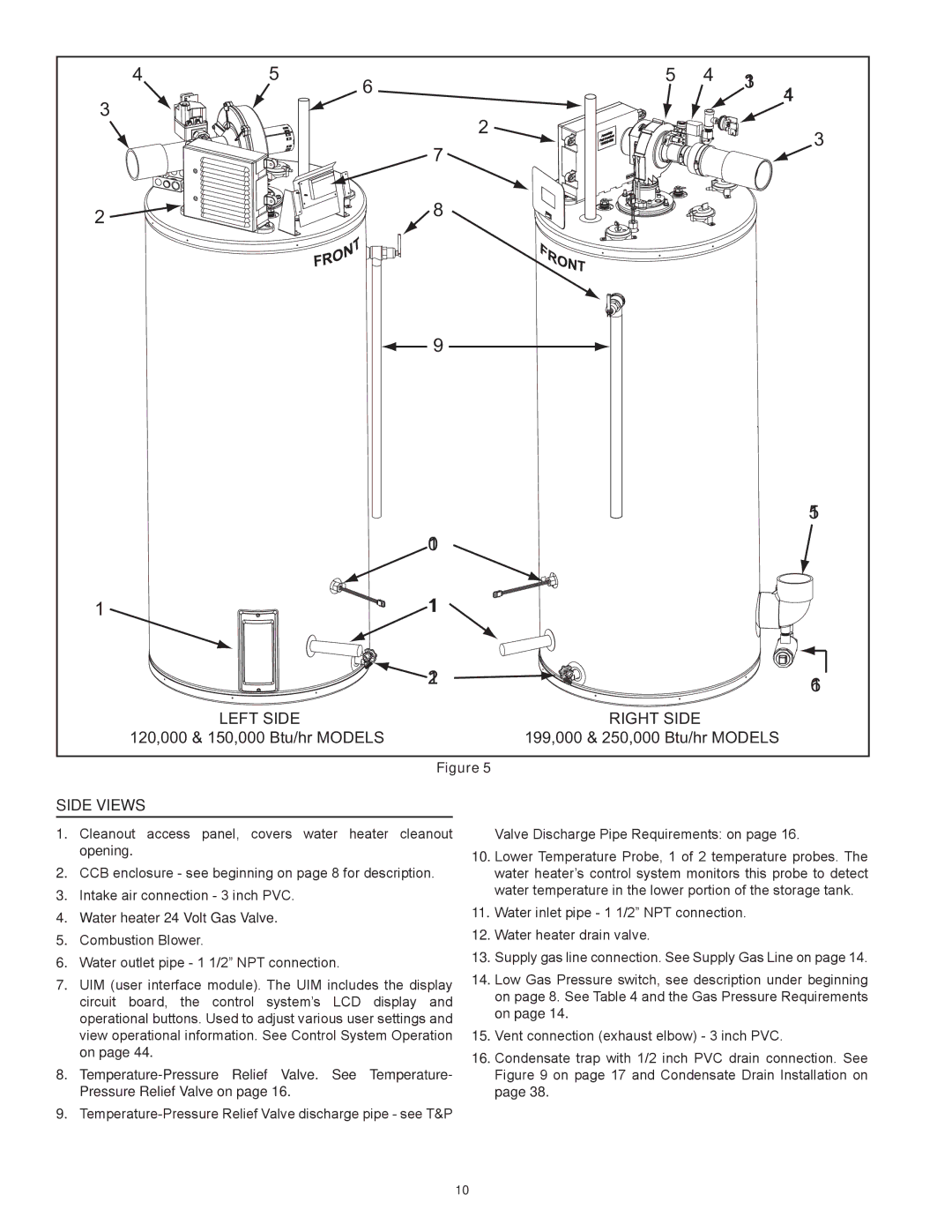
| LEFT SIDE |
| RIGHT SIDE |
|
|
|
120,000 & 150,000 Btu/hr MODELS | 199,000 & 250,000 Btu/hr MODELS | |||||
Figure 5
Side Views
1.Cleanout access panel, covers water heater cleanout opening.
2.CCB enclosure - see beginning on page 8 for description.
3.Intake air connection - 3 inch PVC.
4.Water heater 24 Volt Gas Valve.
5.Combustion Blower.
6.Water outlet pipe - 1 1/2” NPT connection.
7.UIM (user interface module). The UIM includes the display circuit board, the control system’s LCD display and operational buttons. Used to adjust various user settings and view operational information. See Control System Operation on page 44.
8.
9.
Valve Discharge Pipe Requirements: on page 16.
10.Lower Temperature Probe, 1 of 2 temperature probes. The water heater’s control system monitors this probe to detect water temperature in the lower portion of the storage tank.
11.Water inlet pipe - 1 1/2” NPT connection.
12.Water heater drain valve.
13.Supply gas line connection. See Supply Gas Line on page 14.
14.Low Gas Pressure switch, see description under beginning on page 8. See Table 4 and the Gas Pressure Requirements on page 14.
15.Vent connection (exhaust elbow) - 3 inch PVC.
16.Condensate trap with 1/2 inch PVC drain connection. See Figure 9 on page 17 and Condensate Drain Installation on page 38.
10