Venting Installation Sequence
1.Read the General Venting Instructions on page 22 and Venting Requirements on page 24 before proceeding. These instructions and requirements must be followed on all installations.
2. Determine whether the water heater will be installed in a Power Vent or Direct Vent configuration and which vent system arrangement will be used for the installation. See the various venting arrangements on pages 34 and 35.
3.Proceed to the applicable instructions:
•Power Vent Installation on page 25.
•Direct Vent Installation on page 25.
Power Vent Installation
1.Read the General Venting Instructions on page 22 and Venting Requirements on page 24 before proceeding. These instructions and requirements must be followed in addition to the instructions below that are specific for Power Vent configurations.
2.Determine which Power Vent arrangement will be used for the installation; vertical or horizontal termination. See Figure 40 and Figure 41 on page 34.
3.Determine the vent pipe size for the installation, see Venting
Requirements on page 24.
4.Plan the layout of the vent piping backwards from the termination point outdoors to the water heater. Layout the vent piping to use a minimum of pipe and elbows.
5.Install the termination first.
If the vent piping will terminate vertically, through a roof, see Vertical Termination Installation on page 27.
If the vent piping will terminate horizontally, through a sidewall, see Sidewall Termination Installation on page 29.
6.When installation of the termination is complete install necessary piping and fittings to route the vent piping back to the water heater.
7.The vent pipe must be supported properly to avoid bending or failure. The water heater manufacturer recommends that the vent pipe be supported every 5 feet (152 cm) of vertical run and every 3 feet (91 cm) of horizontal run.
8.Do not install the vent piping in a manner that will allow water to be trapped in the piping.
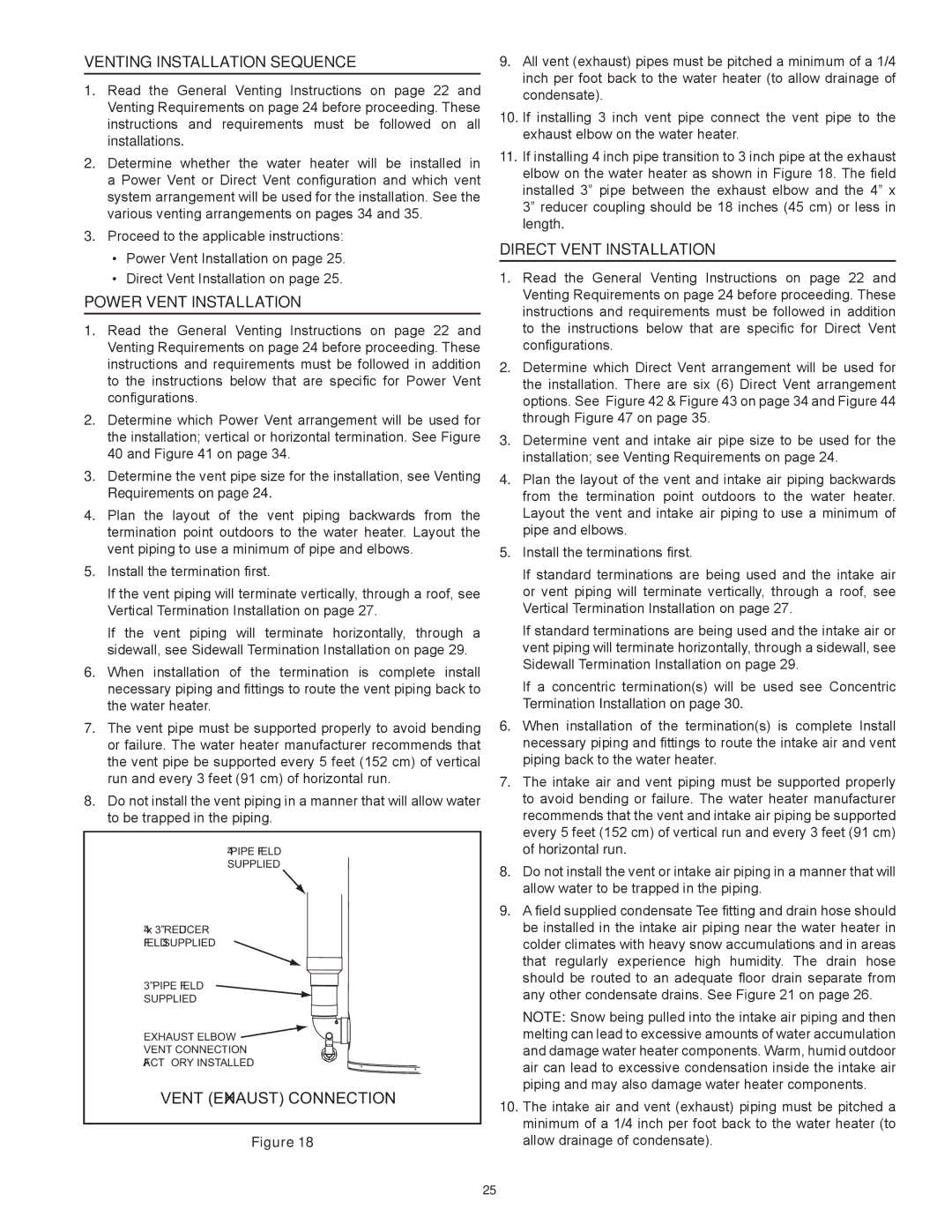
4” PIPE FIELD SUPPLIED
4” x 3” REDUCER FIELD SUPPLIED ![]()
3” PIPE FIELD SUPPLIED
EXHAUST ELBOW ![]()
VENT CONNECTION
FACTORY INSTALLED
VENT (EXHAUST) CONNECTION
Figure 18
9.All vent (exhaust) pipes must be pitched a minimum of a 1/4 inch per foot back to the water heater (to allow drainage of condensate).
10.If installing 3 inch vent pipe connect the vent pipe to the exhaust elbow on the water heater.
11.If installing 4 inch pipe transition to 3 inch pipe at the exhaust elbow on the water heater as shown in Figure 18. The field installed 3” pipe between the exhaust elbow and the 4” x 3” reducer coupling should be 18 inches (45 cm) or less in length.
Direct Vent Installation
1.Read the General Venting Instructions on page 22 and Venting Requirements on page 24 before proceeding. These instructions and requirements must be followed in addition to the instructions below that are specific for Direct Vent configurations.
2.Determine which Direct Vent arrangement will be used for the installation. There are six (6) Direct Vent arrangement options. See Figure 42 & Figure 43 on page 34 and Figure 44 through Figure 47 on page 35.
3.Determine vent and intake air pipe size to be used for the installation; see Venting Requirements on page 24.
4.Plan the layout of the vent and intake air piping backwards from the termination point outdoors to the water heater. Layout the vent and intake air piping to use a minimum of pipe and elbows.
5.Install the terminations first.
If standard terminations are being used and the intake air or vent piping will terminate vertically, through a roof, see Vertical Termination Installation on page 27.
If standard terminations are being used and the intake air or vent piping will terminate horizontally, through a sidewall, see Sidewall Termination Installation on page 29.
If a concentric termination(s) will be used see Concentric
Termination Installation on page 30.
6.When installation of the termination(s) is complete Install necessary piping and fittings to route the intake air and vent piping back to the water heater.
7.The intake air and vent piping must be supported properly to avoid bending or failure. The water heater manufacturer recommends that the vent and intake air piping be supported every 5 feet (152 cm) of vertical run and every 3 feet (91 cm) of horizontal run.
8.Do not install the vent or intake air piping in a manner that will allow water to be trapped in the piping.
9.A field supplied condensate Tee fitting and drain hose should be installed in the intake air piping near the water heater in colder climates with heavy snow accumulations and in areas that regularly experience high humidity. The drain hose should be routed to an adequate floor drain separate from any other condensate drains. See Figure 21 on page 26.
Note: Snow being pulled into the intake air piping and then melting can lead to excessive amounts of water accumulation and damage water heater components. Warm, humid outdoor air can lead to excessive condensation inside the intake air piping and may also damage water heater components.
10.The intake air and vent (exhaust) piping must be pitched a minimum of a 1/4 inch per foot back to the water heater (to allow drainage of condensate).
25