Installation Considerations
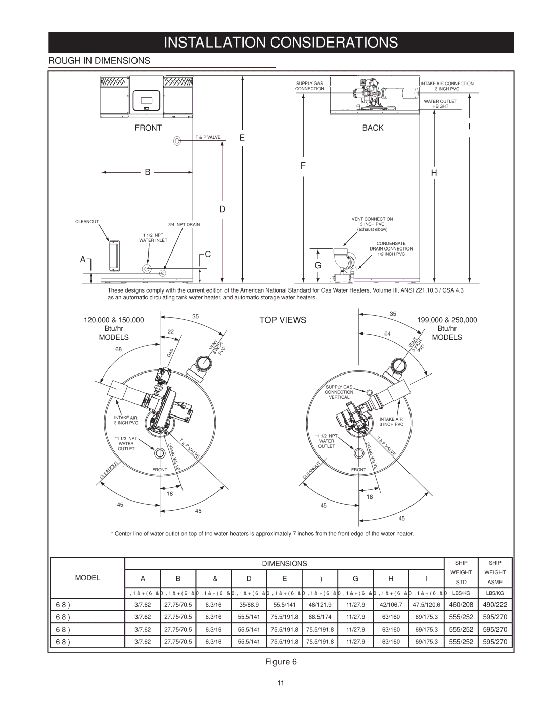
Rough In Dimensions
CLEANOUT
A
SUPPLY GAS
CONNECTION
FRONT |
| E |
| T & P VALVE | |
|
| |
B |
| F |
|
|
D
3/4” NPT DRAIN
1 1/2” NPT
WATER INLET
C
G
| INTAKE AIR CONNECTION |
| 3 INCH PVC |
| WATER OUTLET |
| HEIGHT |
BACK | I |
H
VENT CONNECTION
3 INCH PVC
(exhaust elbow)
CONDENSATE
DRAIN CONNECTION
1/2 INCH PVC
These designs comply with the current edition of the American National Standard for Gas Water Heaters, Volume III, ANSI Z21.10.3 / CSA 4.3 as an automatic circulating tank water heater, and automatic storage water heaters.
120,000 & 150,000
Btu/hr
MODELS
68°
22°
GAS
35°
VENT | |
3 | INCH |
PVC | |
TOP VIEWS
| 35° |
| 199,000 & 250,000 | ||
|
|
|
| ||
|
|
|
|
| Btu/hr |
64° |
|
|
| ||
| VENT | MODELS | |||
|
|
| |||
|
|
|
| ||
3 | INCH |
| |||
PVC |
| ||||
SUPPLY GAS
CONNECTION![]()
![]()
VERTICAL
INTAKE AIR 3 INCH PVC
*1 1/2” NPT
WATER
OUTLET
|
|
|
|
|
| T |
|
|
|
|
| U | |
|
|
|
| O |
| |
|
|
| N |
|
| |
|
| A |
|
|
| |
| E |
|
|
|
| |
L |
|
|
|
|
| |
C |
|
|
|
|
|
|
45°
| T | |
D | & | |
| R | P |
| A | V |
| I | A |
| N | L |
|
| V |
| V | E |
| A |
|
| L |
|
FRONT | V |
|
E | ||
18°
45°
*1 1/2” NPT
WATER
OUTLET
|
|
|
|
|
| T |
|
|
|
|
| U | |
|
|
|
| O |
| |
|
|
| N |
|
| |
|
| A |
|
|
| |
| E |
|
|
|
| |
L |
|
|
|
|
| |
C |
|
|
|
|
|
|
45°
|
| INTAKE AIR | |
|
| 3 INCH PVC | |
| T | ||
|
| & | |
D | P | ||
RA | V | ||
AL | |||
| I | ||
| N | V | |
|
| E | |
| V |
| |
| A |
| |
| L |
| |
FRONT | V |
| |
E | |||
18°
45°
* Center line of water outlet on top of the water heaters is approximately 7 inches from the front edge of the water heater.
|
|
|
| DIMENSIONS |
|
|
| SHIP | SHIP | |||
MODEL | A | B | C | D | E | F | G | H | I | WEIGHT | WEIGHT | |
STD | ASME | |||||||||||
|
|
|
|
|
|
|
|
|
| |||
|
|
|
|
|
|
|
|
|
|
|
| |
| INCHES/CM | INCHES/CM | INCHES/CM | INCHES/CM | INCHES/CM | INCHES/CM | INCHES/CM | INCHES/CM | INCHES/CM | LBS/KG | LBS/KG | |
|
|
|
|
|
|
|
|
|
|
|
| |
SUF 60 120 | 3/7.62 | 27.75/70.5 | 6.3/16 | 35/88.9 | 55.5/141 | 48/121.9 | 11/27.9 | 42/106.7 | 47.5/120.6 | 460/208 | 490/222 | |
SUF 100 150 | 3/7.62 | 27.75/70.5 | 6.3/16 | 55.5/141 | 75.5/191.8 | 68.5/174 | 11/27.9 | 63/160 | 69/175.3 | 555/252 | 595/270 | |
SUF 100 199 | 3/7.62 | 27.75/70.5 | 6.3/16 | 55.5/141 | 75.5/191.8 | 75.5/191.8 | 11/27.9 | 63/160 | 69/175.3 | 555/252 | 595/270 | |
SUF 100 250 | 3/7.62 | 27.75/70.5 | 6.3/16 | 55.5/141 | 75.5/191.8 | 75.5/191.8 | 11/27.9 | 63/160 | 69/175.3 | 555/252 | 595/270 | |
Figure 6
11