Temperatures Menu (cont) |
|
|
| |
| Description/Action | Display |
| |
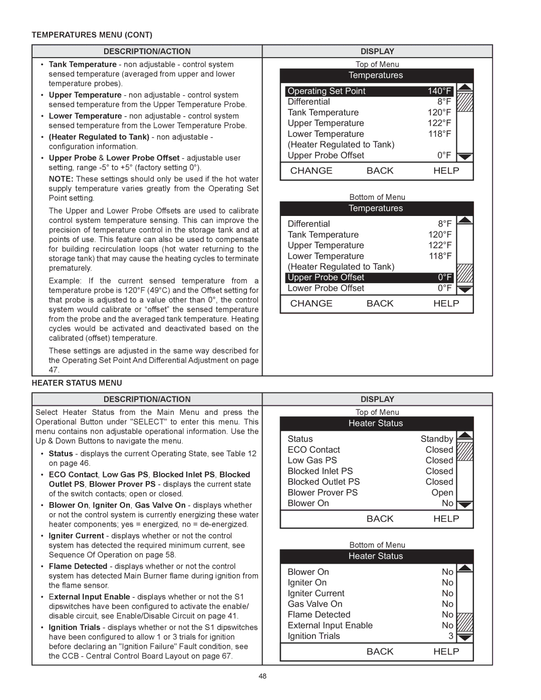
• Tank Temperature - non adjustable - control system | Top of Menu |
| ||
| sensed temperature (averaged from upper and lower | Temperatures |
| |
| temperature probes). | Operating Set Point |
| 140°F |
• | Upper Temperature - non adjustable - control system |
| ||
Differential |
| 8°F | ||
| sensed temperature from the Upper Temperature Probe. |
| ||
• | Lower Temperature - non adjustable - control system | Tank Temperature |
| 120°F |
Upper Temperature |
| 122°F | ||
| sensed temperature from the Lower Temperature Probe. |
| ||
• | (Heater Regulated to Tank) - non adjustable - | Lower Temperature |
| 118°F |
(Heater Regulated to Tank) |
| |||
| configuration information. |
| ||
• Upper Probe & Lower Probe Offset - adjustable user | Upper Probe Offset |
| 0°F | |
| setting, range | CHANGE | BACK | HELP |
| Note: These settings should only be used if the hot water | |||
|
|
|
| |
| supply temperature varies greatly from the Operating Set | Bottom of Menu |
| |
| Point setting. |
| ||
| The Upper and Lower Probe Offsets are used to calibrate | Temperatures |
| |
| control system temperature sensing. This can improve the | Differential |
| 8°F |
| precision of temperature control in the storage tank and at |
| ||
| Tank Temperature |
| 120°F | |
| points of use. This feature can also be used to compensate |
| ||
| Upper Temperature |
| 122°F | |
| for building recirculation loops (hot water returning to the |
| ||
| Lower Temperature |
| 118°F | |
| storage tank) that may cause the heating cycles to terminate |
| ||
| prematurely. | (Heater Regulated to Tank) |
| |
| Example: If the current sensed temperature from a | Upper Probe Offset |
| 0°F |
| Lower Probe Offset |
| 0°F | |
| temperature probe is 120°F (49°C) and the Offset setting for |
| ||
| that probe is adjusted to a value other than 0°, the control | CHANGE | BACK | HELP |
| system would calibrate or “offset” the sensed temperature | |||
|
|
|
| |
| from the probe and the averaged tank temperature. Heating |
|
|
|
| cycles would be activated and deactivated based on the |
|
|
|
| calibrated (offset) temperature. |
|
|
|
These settings are adjusted in the same way described for the Operating Set Point And Differential Adjustment on page 47.
Heater Status Menu
| Description/Action | Display |
| |
Select Heater Status from the Main Menu and press the | Top of Menu |
| ||
Operational Button under "SELECT" to enter this menu. This | Heater Status |
| ||
menu contains non adjustable operational information. Use the | Status | Standby | ||
Up & Down Buttons to navigate the menu. | ||||
• Status - displays the current Operating State, see Table 12 | ECO Contact | Closed | ||
Low Gas PS | Closed | |||
| on page 46. | |||
• | ECO Contact, Low Gas PS, Blocked Inlet PS, Blocked | Blocked Inlet PS | Closed | |
Blocked Outlet PS | Closed | |||
| Outlet PS, Blower Prover PS - displays the current state | |||
| of the switch contacts; open or closed. | Blower Prover PS | Open | |
• Blower On, Igniter On, Gas Valve On - displays whether | Blower On | No | ||
| or not the control system is currently energizing these water | BACK | HELP | |
| heater components; yes = energized, no = | |||
|
|
| ||
• Igniter Current - displays whether or not the control | Bottom of Menu |
| ||
| system has detected the required minimum current, see |
| ||
| Sequence Of Operation on page 58. | Heater Status |
| |
• | Flame Detected - displays whether or not the control | Blower On | No | |
| system has detected Main Burner flame during ignition from | |||
| Igniter On | No | ||
| the flame sensor. | |||
• | External Input Enable - displays whether or not the S1 | Igniter Current | No | |
Gas Valve On | No | |||
| dipswitches have been configured to activate the enable/ | |||
| disable circuit, see Enable/Disable Circuit on page 41. | Flame Detected | No | |
• Ignition Trials - displays whether or not the S1 dipswitches | External Input Enable | No | ||
| have been configured to allow 1 or 3 trials for ignition | Ignition Trials | 3 | |
| before declaring an "Ignition Failure" Fault condition, see | BACK | HELP | |
| the CCB - Central Control Board Layout on page 67. | |||
|
|
| ||
48