TABLE 15
UN-LIME® Professional Delimer
Part Number | Description |
9005416105 | 4 - 1 gallon (case) |
9005417105 | 1 - 5 gallon |
Powered Anode Rods
To insure a long,
Note: Follow the instructions to drain the water heater storage tank on page 64 first. Remove the powered anodes from the water heater by loosening the 3/4" NPT bushing that forms the top of the anodes. Do not disassemble the retaining nut and wire terminal from the top while installed in the water heater, the anode's electrode may fall inside the tank. Remove the entire anode rod from the water heater prior to inspection. Clean the anode rods with a soft cloth and reinstall. Follow the instructions for filling the water heater on page 52 when finished.
Drain Valve and Access Panels
The water heaters covered in this manual are equipped with a drain valve, see Features And Components on page 7 for location. The water heaters covered in this manual are also equipped with a cleanout opening for sediment and lime scale removal. See Figure 63 on page 65.
Temperature-Pressure Relief Valve Test
![]()
![]() Burn hazard.
Burn hazard.
![]() Hot water discharge.
Hot water discharge.
![]() Keep clear of Temperature- Pressure Relief Valve discharge outlet.
Keep clear of Temperature- Pressure Relief Valve discharge outlet.
It is recommended that the
When checking the
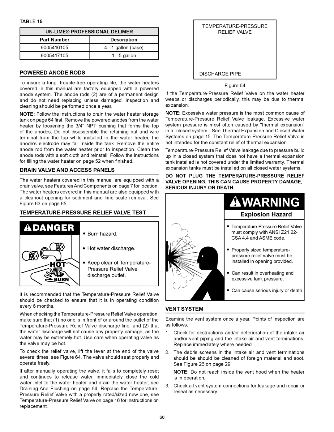
To check the relief valve, lift the lever at the end of the valve several times, see Figure 64. The valve should seat properly and operate freely.
If after manually operating the valve, it fails to completely reset and continues to release water, immediately close the cold water inlet to the water heater and drain the water heater, see Draining And Flushing on page 64. Replace the Temperature- Pressure Relief Valve with a properly rated/sized new one, see
TEMPERATURE-PRESSURE
RELIEF VALVE
DISCHARGE PIPE
Figure 64
If the
Note: Excessive water pressure is the most common cause of
Do not plug the
Explosion Hazard
![]()
Properly sized temperature- pressure relief valve must be installed in opening provided.
Can result in overheating and excessive tank pressure.
Can cause serious injury or death.
Vent System
Examine the vent system once a year. Points of inspection are as follows:
1.Check for obstructions and/or deterioration of the intake air and/or vent piping and the intake air and vent terminations. Replace immediately where needed.
2.The debris screens in the intake air and vent terminations should be should be cleaned of foreign material and soot. See Figure 26 on page 29.
Note: Do not reach inside the vent hood when the heater is in operation.
3.Check all vent system connections for leakage and repair or reseal as necessary.
66