11.If installing 3 inch vent pipe connect the vent pipe to the exhaust elbow on the water heater.
12.If installing 4 inch vent pipe transition to 3 inch pipe at the exhaust elbow on the water heater as shown in Figure 18 on page 25. The field installed 3” pipe between the exhaust elbow and the 4” x 3” reducer coupling should be 18 inches (45 cm) or less in length.
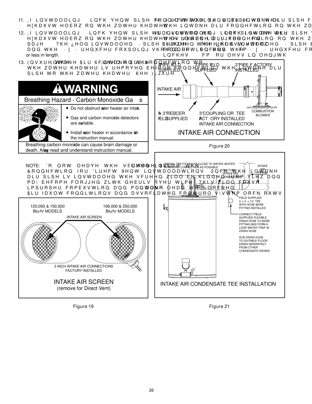
13.Ensure the Intake Air Screen on the Intake Air Connection to the water heater is removed before connecting the intake air pipe to the water heater. See Figure 19.
Breathing Hazard - Carbon Monoxide Gas
![]() Do not obstruct water heater air intake.
Do not obstruct water heater air intake.
![]() Gas and carbon monoxide detectors are available.
Gas and carbon monoxide detectors are available.
![]() Install water heater in accordance with the instruction manual.
Install water heater in accordance with the instruction manual.
Breathing carbon monoxide can cause brain damage or death. Always read and understand instruction manual.
Note: Do not leave the screen inside the Intake Air Connection for Direct Vent installations. Once the intake air pipe is installed the screen will be hidden from view and may become clogged with debris over time. This will cause improper combustion and may also lead to Blocked Intake Air fault conditions and associated control system lock outs.
120,000 & 150,000 | 199,000 & 250,000 |
Btu/hr MODELS | Btu/hr MODELS |
| INTAKE AIR SCREEN |
3 INCH INTAKE AIR CONNECTIONS | |
| FACTORY INSTALLED |
INTAKE AIR SCREEN | |
(remove for Direct Vent) | |
14.If installing 3 inch intake air pipe connect the intake air pipe to the intake air connection on the water heater.
15.If installing 4 inch intake air pipe transition to 3 inch pipe at the intake air connection on the water heater as shown in Figure 20. The field installed 3” pipe between the intake air connection and the 4” x 3” reducer coupling should be 18 inches (45 cm) or less in length.
4” PIPE FIELD | 3” PIPE FIELD | 3” PIPE FACTORY | |
SUPPLIED | SUPPLIED | INSTALLED | |
INTAKE AIR |
|
|
|
4” x 3” REDUCER | 3” COUPLING OR TEE | COMBUSTION | |
BLOWER | |||
FIELD SUPPLIED | FACTORY INSTALLED |
| |
INTAKE AIR CONNECTION
INTAKE AIR CONNECTION
Figure 20
INSTALL TEE FITTING AS CLOSE TO WATER HEATER | INTAKE | |
INTAKE AIR CONNECTION AS POSSIBLE | ||
AIR | ||
FACTORY | ||
PIPING | ||
INTAKE AIR | ||
CONNECTION | ||
| FIELD SUPPLIED | |
| 3” x 3” x 1/2” TEE | |
| WITH HOSE BARB | |
| FITTING INSTALLED | |
| CONNECT FIELD | |
| SUPPLIED FLEXIBLE | |
| DRAIN HOSE TO BARB | |
| FITTING AND FORM A | |
| LOOP WATER TRAP IN | |
| DRAIN HOSE | |
| RUN DRAIN HOSE | |
| TO SUITABLE FLOOR | |
| DRAIN SEPARATELY | |
| FROM OTHER | |
| CONDENSATE DRAINS | |
INTAKE AIR CONDENSATE TEE INSTALLATION
Figure 19 | Figure 21 |
26