Temperature-Pressure Relief Valve
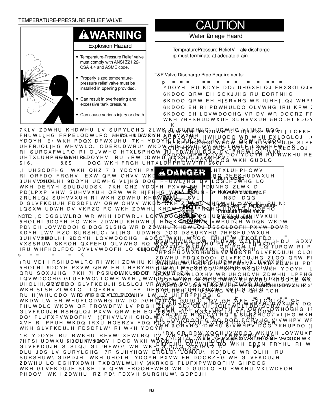
Explosion Hazard
![]()
Properly sized temperature- pressure relief valve must be installed in opening provided.
Can result in overheating and excessive tank pressure.
Can cause serious injury or death.
This water heater is provided with a properly rated/sized and certified combination
If replaced, the new T&P valve must meet the requirements of local codes, but not less than a combination Temperature- Pressure Relief Valve rated/sized and certified as indicated in the above paragraph. The new valve must be marked with a maximum set pressure not to exceed the marked hydrostatic working pressure of the water heater (150 psi = 1,035 kPa) and a discharge capacity not less than the water heater Btu/hr or kW input rate as shown on the water heater’s model rating label.
Note: In addition to the factory installed
For safe operation of the water heater, the
No valve or other obstruction is to be placed between the
CAUTION
Water Damage Hazard
•
T&P Valve Discharge Pipe Requirements:
•Shall not be smaller in size than the outlet pipe size of the valve, or have any reducing couplings or other restrictions.
•Shall not be plugged or blocked.
•Shall not be exposed to freezing temperatures.
•Shall be of material listed for hot water distribution.
•Shall be installed so as to allow complete drainage of both the
•Must terminate a maximum of six inches above a floor drain or external to the building. In cold climates, it is recommended that the discharge pipe be terminated at an adequate drain inside the building.
•Shall not have any valve or other obstruction between the relief valve and the drain.
![]() Burn hazard.
Burn hazard.
![]() Hot water discharge.
Hot water discharge.
![]() Keep clear of Temperature- Pressure Relief Valve discharge outlet.
Keep clear of Temperature- Pressure Relief Valve discharge outlet.
The
Note: The purpose of a
If you do not understand these instructions or have any questions regarding the
16