Vertical Termination Installation
1.Determine the location for the termination(s).
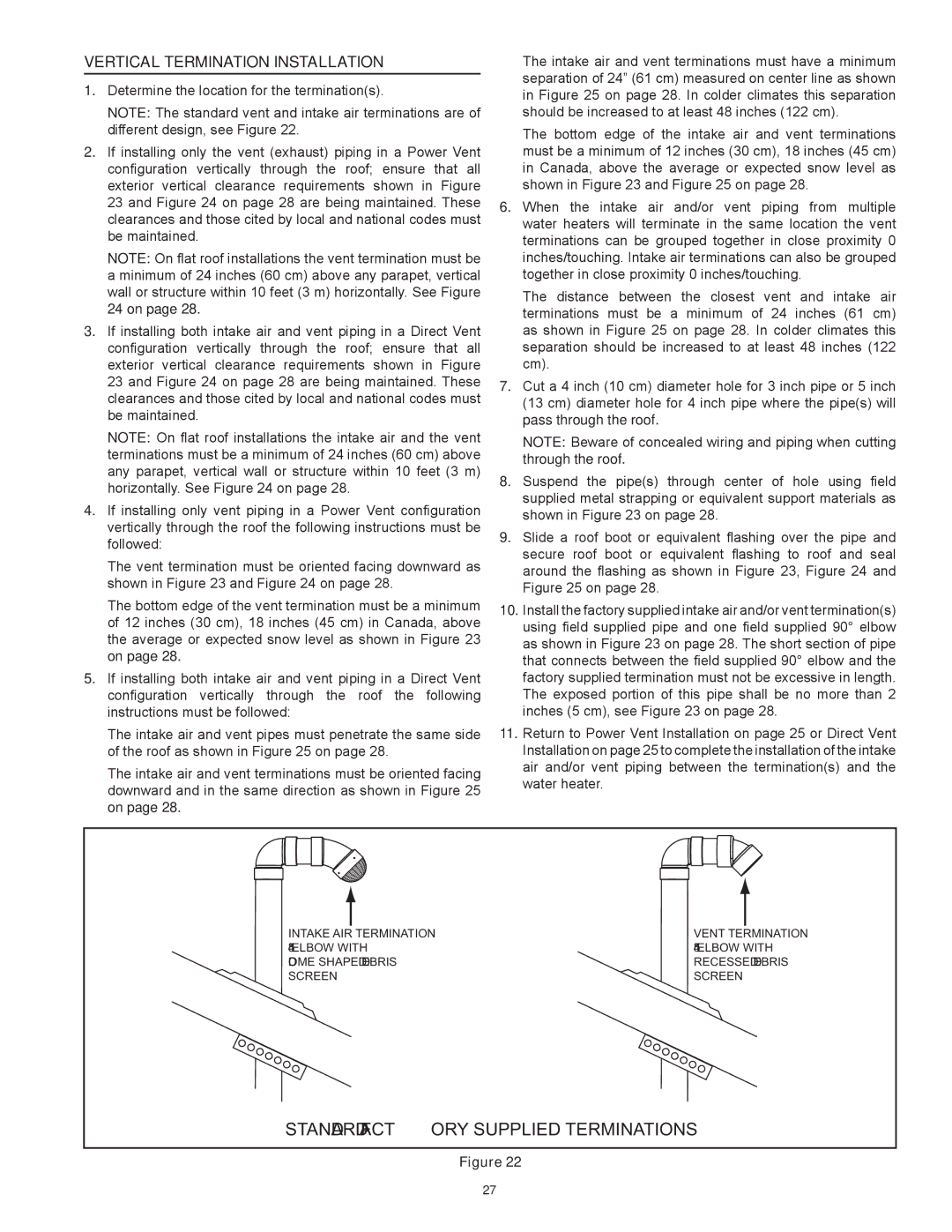
Note: The standard vent and intake air terminations are of different design, see Figure 22.
2.If installing only the vent (exhaust) piping in a Power Vent configuration vertically through the roof; ensure that all exterior vertical clearance requirements shown in Figure 23 and Figure 24 on page 28 are being maintained. These clearances and those cited by local and national codes must be maintained.
Note: On flat roof installations the vent termination must be a minimum of 24 inches (60 cm) above any parapet, vertical wall or structure within 10 feet (3 m) horizontally. See Figure
24 on page 28.
3.If installing both intake air and vent piping in a Direct Vent configuration vertically through the roof; ensure that all exterior vertical clearance requirements shown in Figure 23 and Figure 24 on page 28 are being maintained. These clearances and those cited by local and national codes must be maintained.
Note: On flat roof installations the intake air and the vent terminations must be a minimum of 24 inches (60 cm) above any parapet, vertical wall or structure within 10 feet (3 m) horizontally. See Figure 24 on page 28.
4.If installing only vent piping in a Power Vent configuration vertically through the roof the following instructions must be followed:
The vent termination must be oriented facing downward as shown in Figure 23 and Figure 24 on page 28.
The bottom edge of the vent termination must be a minimum of 12 inches (30 cm), 18 inches (45 cm) in Canada, above the average or expected snow level as shown in Figure 23 on page 28.
5.If installing both intake air and vent piping in a Direct Vent configuration vertically through the roof the following instructions must be followed:
The intake air and vent pipes must penetrate the same side of the roof as shown in Figure 25 on page 28.
The intake air and vent terminations must be oriented facing downward and in the same direction as shown in Figure 25 on page 28.
The intake air and vent terminations must have a minimum separation of 24” (61 cm) measured on center line as shown in Figure 25 on page 28. In colder climates this separation should be increased to at least 48 inches (122 cm).
The bottom edge of the intake air and vent terminations must be a minimum of 12 inches (30 cm), 18 inches (45 cm) in Canada, above the average or expected snow level as shown in Figure 23 and Figure 25 on page 28.
6.When the intake air and/or vent piping from multiple water heaters will terminate in the same location the vent terminations can be grouped together in close proximity 0 inches/touching. Intake air terminations can also be grouped together in close proximity 0 inches/touching.
The distance between the closest vent and intake air terminations must be a minimum of 24 inches (61 cm) as shown in Figure 25 on page 28. In colder climates this separation should be increased to at least 48 inches (122 cm).
7.Cut a 4 inch (10 cm) diameter hole for 3 inch pipe or 5 inch (13 cm) diameter hole for 4 inch pipe where the pipe(s) will pass through the roof.
Note: Beware of concealed wiring and piping when cutting through the roof.
8.Suspend the pipe(s) through center of hole using field supplied metal strapping or equivalent support materials as shown in Figure 23 on page 28.
9.Slide a roof boot or equivalent flashing over the pipe and secure roof boot or equivalent flashing to roof and seal around the flashing as shown in Figure 23, Figure 24 and Figure 25 on page 28.
10.Install the factory supplied intake air and/or vent termination(s) using field supplied pipe and one field supplied 90° elbow as shown in Figure 23 on page 28. The short section of pipe that connects between the field supplied 90° elbow and the factory supplied termination must not be excessive in length. The exposed portion of this pipe shall be no more than 2 inches (5 cm), see Figure 23 on page 28.
11.Return to Power Vent Installation on page 25 or Direct Vent Installation on page 25 to complete the installation of the intake air and/or vent piping between the termination(s) and the water heater.
INTAKE AIR |
| TERMINATION | VENT |
| TERMINATION |
|
| ||||
|
| ||||
45° ELBOW WITH | 45° ELBOW WITH | ||||
DOME SHAPED DEBRIS | RECESSED DEBRIS | ||||
SCREEN | SCREEN | ||||
STANDARD FACTORY SUPPLIED TERMINATIONS
Figure 22
27