Supply Gas Line Installation
Contact your local gas utility company to ensure that adequate gas service is available and to review applicable installation codes for your area.
Be sure that the gas meter has sufficient capacity to supply the rated gas input of the water heater as well as the requirements of all other gas fired equipment supplied by the meter. If the gas meter is undersized, the gas company will have to install a properly sized gas meter.
Fire and Explosion Hazard
![]() Do not use water heater with any gas other than the gas shown on the rating label.
Do not use water heater with any gas other than the gas shown on the rating label.
![]() Excessive gas pressure to gas valve can cause serious injury or death.
Excessive gas pressure to gas valve can cause serious injury or death.
![]() Turn off gas lines during installation.
Turn off gas lines during installation.
![]() Contact a qualified installer or service agency for installation and service.
Contact a qualified installer or service agency for installation and service.
Make sure gas supplied is same type listed on the water heater’s rating label.
The water heaters covered in this manual are not intended for operation at higher than 10.5” W. C. (2.62 kPa) for natural gas and 14.0” W. C. (3.49 kPa) for propane gas supply pressure, see Table 4 on page 14. The water heaters covered in this manual require supply gas regulators to maintain required supply gas pressure. Exposure to higher gas supply pressure may cause damage to the gas controls which could result in fire or explosion. If overpressure has occurred such as through improper testing of gas lines or malfunction of the supply system the water heater’s gas valve must be checked for safe operation by a Qualified Service Agency.
Ensure supply regulator vent lines and the safety vent valves are protected against blockage. These are components of the gas supply system, not the water heater. Vent blockage may occur during ice storms.
It is important to guard against gas valve fouling from contaminants in the gas ways. Such fouling may cause improper operation, fire or explosion. If copper supply lines are used they must be internally tinned and certified for gas service.
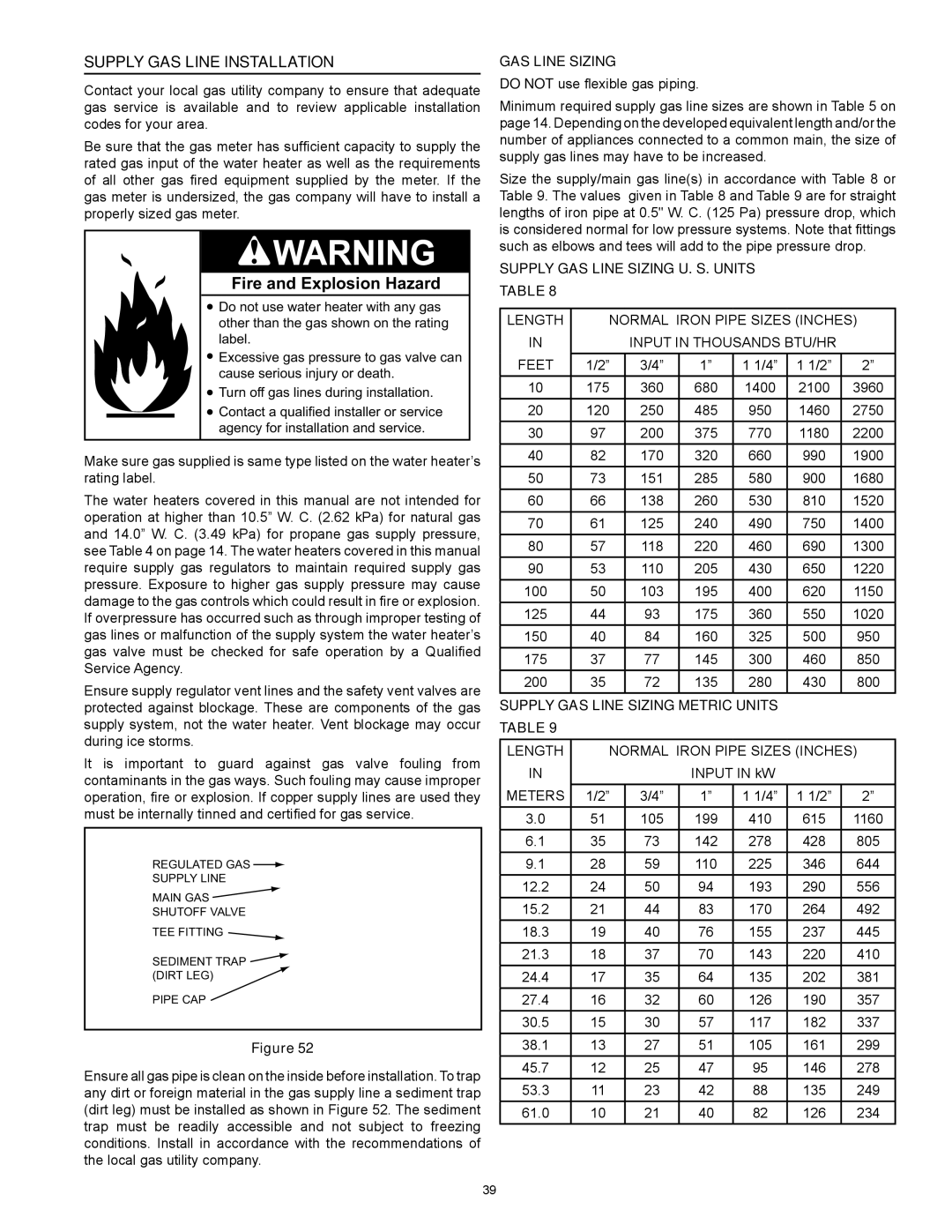
REGULATED GAS ![]()
SUPPLY LINE
MAIN GAS ![]()
SHUTOFF VALVE
TEE FITTING ![]()
SEDIMENT TRAP ![]() (DIRT LEG)
(DIRT LEG) ![]()
PIPE CAP
Figure 52
Ensure all gas pipe is clean on the inside before installation. To trap any dirt or foreign material in the gas supply line a sediment trap (dirt leg) must be installed as shown in Figure 52. The sediment trap must be readily accessible and not subject to freezing conditions. Install in accordance with the recommendations of the local gas utility company.
Gas Line Sizing
Do not use flexible gas piping.
Minimum required supply gas line sizes are shown in Table 5 on page 14. Depending on the developed equivalent length and/or the number of appliances connected to a common main, the size of supply gas lines may have to be increased.
Size the supply/main gas line(s) in accordance with Table 8 or Table 9. The values given in Table 8 and Table 9 are for straight lengths of iron pipe at 0.5" W. C. (125 Pa) pressure drop, which is considered normal for low pressure systems. Note that fittings such as elbows and tees will add to the pipe pressure drop.
Supply Gas Line Sizing U. S. Units
Table 8
Length | Normal Iron Pipe Sizes (inches) | |||||
in |
| Input in Thousands Btu/hr |
| |||
Feet | 1/2” | 3/4” | 1” | 1 1/4” | 1 1/2” | 2” |
10 | 175 | 360 | 680 | 1400 | 2100 | 3960 |
20 | 120 | 250 | 485 | 950 | 1460 | 2750 |
30 | 97 | 200 | 375 | 770 | 1180 | 2200 |
40 | 82 | 170 | 320 | 660 | 990 | 1900 |
50 | 73 | 151 | 285 | 580 | 900 | 1680 |
60 | 66 | 138 | 260 | 530 | 810 | 1520 |
70 | 61 | 125 | 240 | 490 | 750 | 1400 |
80 | 57 | 118 | 220 | 460 | 690 | 1300 |
90 | 53 | 110 | 205 | 430 | 650 | 1220 |
100 | 50 | 103 | 195 | 400 | 620 | 1150 |
125 | 44 | 93 | 175 | 360 | 550 | 1020 |
150 | 40 | 84 | 160 | 325 | 500 | 950 |
175 | 37 | 77 | 145 | 300 | 460 | 850 |
200 | 35 | 72 | 135 | 280 | 430 | 800 |
Supply Gas Line Sizing Metric Units |
|
| ||||
Table 9 |
|
|
|
|
|
|
Length | Normal Iron Pipe Sizes (inches) | |||||
in |
|
| Input in kW |
|
| |
Meters | 1/2” | 3/4” | 1” | 1 1/4” | 1 1/2” | 2” |
3.0 | 51 | 105 | 199 | 410 | 615 | 1160 |
6.1 | 35 | 73 | 142 | 278 | 428 | 805 |
9.1 | 28 | 59 | 110 | 225 | 346 | 644 |
12.2 | 24 | 50 | 94 | 193 | 290 | 556 |
15.2 | 21 | 44 | 83 | 170 | 264 | 492 |
18.3 | 19 | 40 | 76 | 155 | 237 | 445 |
21.3 | 18 | 37 | 70 | 143 | 220 | 410 |
24.4 | 17 | 35 | 64 | 135 | 202 | 381 |
27.4 | 16 | 32 | 60 | 126 | 190 | 357 |
30.5 | 15 | 30 | 57 | 117 | 182 | 337 |
38.1 | 13 | 27 | 51 | 105 | 161 | 299 |
45.7 | 12 | 25 | 47 | 95 | 146 | 278 |
53.3 | 11 | 23 | 42 | 88 | 135 | 249 |
61.0 | 10 | 21 | 40 | 82 | 126 | 234 |
39