Venting Installation
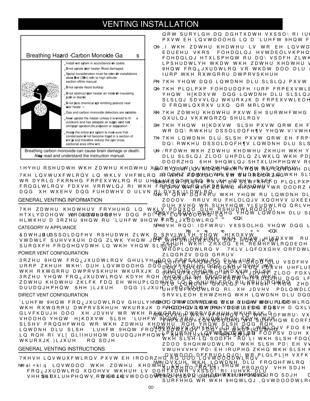
Breathing Hazard - Carbon Monoxide Gas
•Install vent system in accordance with codes.
•Do not operate water heater if flood damaged.
•Special consideration must be taken with installations above 10,000 feet (3,048 m) refer to high altitude section of this manual.
• Do not operate if soot buildup.
• Do not obstruct water heater air intake with insulating jacket or blanket.
• Do not place chemical vapor emitting products near water heater.
• Gas and carbon monoxide detectors are available.
•Never operate the heater unless it is vented to the outdoors and has adequate air supply to avoid risks of improper operation, fire, explosion or asphyxiation.
•Analyze the entire vent system to make sure that condensate will not become trapped in a section of vent pipe and therefore reduce the open cross sectional area of the vent.
Breathing carbon monoxide can cause brain damage or death.
Always read and understand the instruction manual.
Never operate the water heater unless it is vented to the outdoors.
The instructions in this section of the manual must be followed to avoid choked combustion or recirculation of flue gases. Such conditions cause sooting of the combustion chamber, burners and flue tubes and creates a risk of asphyxiation.
General Venting Information
The water heaters covered in this manual are operationally equivalent to Category IV appliances and may be installed in either a Power Vent or Direct Vent configuration.
Category IV Appliance
Category IV appliances operate with a positive vent (exhaust) static pressure and with vent gas temperatures low enough to produce condensate in the vent piping.
Power Vent Configuration
Power Vent configurations derive all combustion air from the room where they are installed and discharge all flue gases to the outdoor atmosphere through a sealed vent (exhaust) pipe. Power vent configurations have one vent pipe connected to the water heater which can be terminated in a vertical or horizontal arrangement. See Figure 40 and Figure 41 on page 34.
Direct Vent Configuration
Direct Vent configurations derive all combustion air directly from the outdoor atmosphere through a sealed intake air pipe and discharge all flue gases to the outdoor atmosphere through a sealed vent (exhaust) pipe. Direct Vent configurations have two pipes connected to the water heater, one vent pipe and one intake air pipe. Direct Vent configurations can be terminated in one of six different arrangements. See Figure 42 on page 34 through Figure 47 on page 35.
General Venting Instructions
These instructions must be followed on all installations.
1.Do not install the water heater in a Power Vent configuration unless there is adequate supply of fresh air, seeAir Requirements on page 18. If the installation space does
not provide an adequate supply of fresh air the water heater must be installed in a Direct Vent configuration.
2.If the water heater is to be installed in a beauty shop, barber shop, cleaning establishment, a laundry with dry cleaning equipment or any space with contaminated air it is imperative that the water heater(s) be installed in a Direct Vent configuration so that all air for combustion is derived from the outdoor atmosphere.
3.The vent and intake air piping must terminate outdoors.
4.The minimum clearance from combustible materials for the vent (exhaust) and intake air piping shall be 0 inches. Vent piping passing through a combustible wall or ceiling must be a continuous run (no joints).
5.The water heater must be protected from freezing downdrafts during shutdown periods.
6.The vent (exhaust) pipe must not be combined or connected to any other appliance’s vent system or chimney.
7.The intake air pipe must not be combined or connected to any other appliance’s intake air piping.
8.Locate the water heater where the vent (exhaust) and intake air piping will remain within the maximum equivalent lengths allowed. See Venting Requirements on page 24.
9.Do not install the vent or intake air piping in a manner that will allow water to be trapped in the piping.
10.Vent pipes must be pitched a minimum of a 1/4 inch per foot back to the water heater (to allow drainage of condensate).
11.Do not anchor the vent or intake air pipe directly to framed walls, floors or ceilings unless rubber isolation pipe hangers are used to prevent vibration noise from being transmitted.
12.Use only approved vent/intake air pipe sizes and materials.
See Venting Requirements on page 24.
13.Use only factory supplied vent and intake air or concentric terminations. See the Venting Requirements on page 24.
14.Do not locate the vent (exhaust) or intake air terminations where they would be objectionable due to noise at the termination(s). This includes locations close to or across from windows and doors.
15.Direct venting into dead air spaces such as alleys, atriums, and inside corners can cause recirculation of flue gases. Recirculation of flue gases will cause sooting, premature failure of the heat exchanger and icing of the combustion air intake during severe cold weather. To prevent the recirculation of flue gases, maintain as much distance as possible between the intake air and vent terminations.
16.Do not locate the vent termination over a public area where condensate or vapor can cause a nuisance or ice hazard.
17.Ensure the screens in the factory supplied terminations are securely installed to prevent blockage in the vent system.
18.Stress levels in pipe/fittings can be significantly increased by improper installation. If rigid pipe clamps are used to hold the pipe in place, or if the pipe cannot move freely through a wall penetration, the pipe may be stressed, or high thermal stresses may be formed when the pipe heats up and expands. Install accordingly to minimize such stresses.
19.Ensure the intake air connection Tee fitting is oriented properly on SUF 199/250 models, see page 23 for instructions.
20.Carefully read the Venting Requirements on page 24 and then proceed to the Venting Installation Sequence on page 25.
22
