Installing Quick Tension Lever
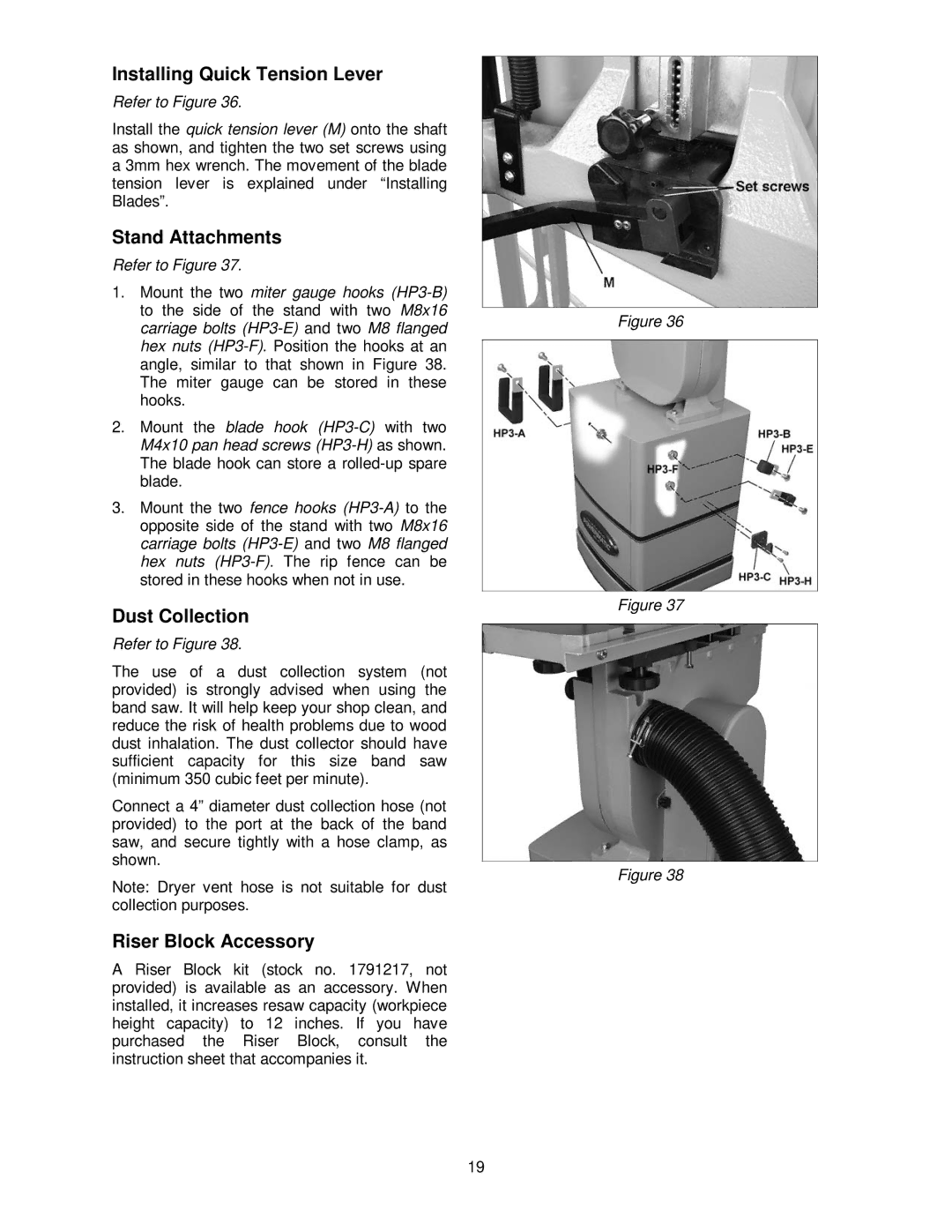
Refer to Figure 36.
Install the quick tension lever (M) onto the shaft as shown, and tighten the two set screws using a 3mm hex wrench. The movement of the blade tension lever is explained under “Installing Blades”.
Stand Attachments
Refer to Figure 37.
1.Mount the two miter gauge hooks
2.Mount the blade hook
3.Mount the two fence hooks
Dust Collection
Refer to Figure 38.
The use of a dust collection system (not provided) is strongly advised when using the band saw. It will help keep your shop clean, and reduce the risk of health problems due to wood dust inhalation. The dust collector should have sufficient capacity for this size band saw (minimum 350 cubic feet per minute).
Connect a 4” diameter dust collection hose (not provided) to the port at the back of the band saw, and secure tightly with a hose clamp, as shown.
Note: Dryer vent hose is not suitable for dust collection purposes.
Riser Block Accessory
A Riser Block kit (stock no. 1791217, not provided) is available as an accessory. When installed, it increases resaw capacity (workpiece height capacity) to 12 inches. If you have purchased the Riser Block, consult the instruction sheet that accompanies it.
Figure 36
Figure 37
Figure 38
19