Installation and Assembly
Tools required for assembly:
hex (Allen) wrenches – 3, 5, 6mm Cross point (Phillips) screwdriver square
straightedge
NOTE: If further clarification is needed for any of the following assembly procedures, consult the exploded views at the back of this manual.
Exposed metal surfaces on the Band Saw, such as the table, have been given a protective coating at the factory. This should be removed with a soft cloth moistened with a light solvent. Do not use gasoline, lacquer thinner, acetone, or other highly volatile solvents for this. Do not use an abrasive pad as it may scratch the polished metal surfaces.
IMPORTANT: The Band Saw must be disconnected from the power source before any assembly procedures!
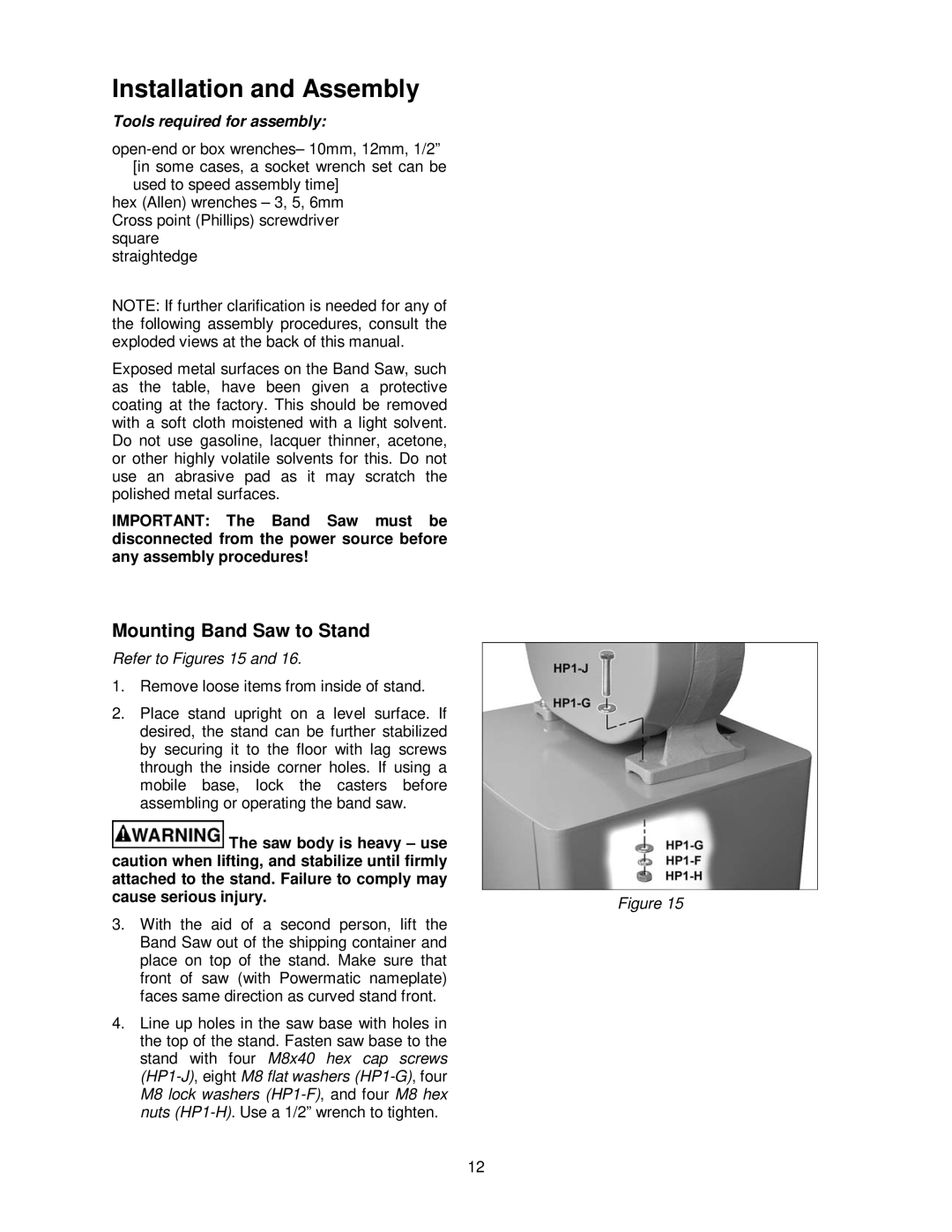
Mounting Band Saw to Stand
Refer to Figures 15 and 16.
1.Remove loose items from inside of stand.
2.Place stand upright on a level surface. If desired, the stand can be further stabilized by securing it to the floor with lag screws through the inside corner holes. If using a mobile base, lock the casters before assembling or operating the band saw.
The saw body is heavy – use |
|
caution when lifting, and stabilize until firmly |
|
attached to the stand. Failure to comply may |
|
cause serious injury. | Figure 15 |
|
3.With the aid of a second person, lift the Band Saw out of the shipping container and place on top of the stand. Make sure that front of saw (with Powermatic nameplate) faces same direction as curved stand front.
4.Line up holes in the saw base with holes in the top of the stand. Fasten saw base to the stand with four M8x40 hex cap screws
12