Leveling the Extension Table
NOTE: Before leveling the extension table, the
Refer to Figures 22 and 24.
1.Position the main table at
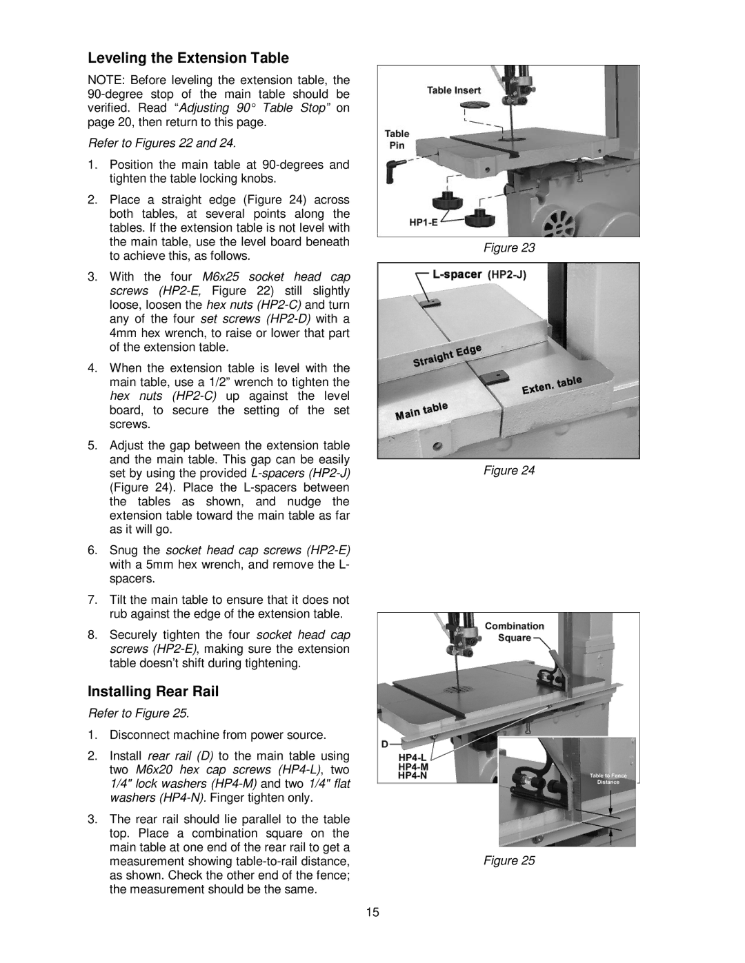
2.Place a straight edge (Figure 24) across both tables, at several points along the tables. If the extension table is not level with the main table, use the level board beneath to achieve this, as follows.
3.With the four M6x25 socket head cap screws
4.When the extension table is level with the main table, use a 1/2” wrench to tighten the hex nuts
5.Adjust the gap between the extension table and the main table. This gap can be easily set by using the provided
6.Snug the socket head cap screws
7.Tilt the main table to ensure that it does not rub against the edge of the extension table.
8.Securely tighten the four socket head cap screws
Installing Rear Rail
Refer to Figure 25.
1.Disconnect machine from power source.
2.Install rear rail (D) to the main table using two M6x20 hex cap screws
3.The rear rail should lie parallel to the table top. Place a combination square on the main table at one end of the rear rail to get a measurement showing
Figure 23
Figure 24
Figure 25
15