NOTE: The pointer’s zero position should be tested later by cutting a straight piece of stock, carefully measuring its width, and comparing it to the scale reading.
Resaw Guide
Refer to Figure 32.
For resawing operations, attach the resaw guide
The resaw guide offers a taller,
Blower Nozzle
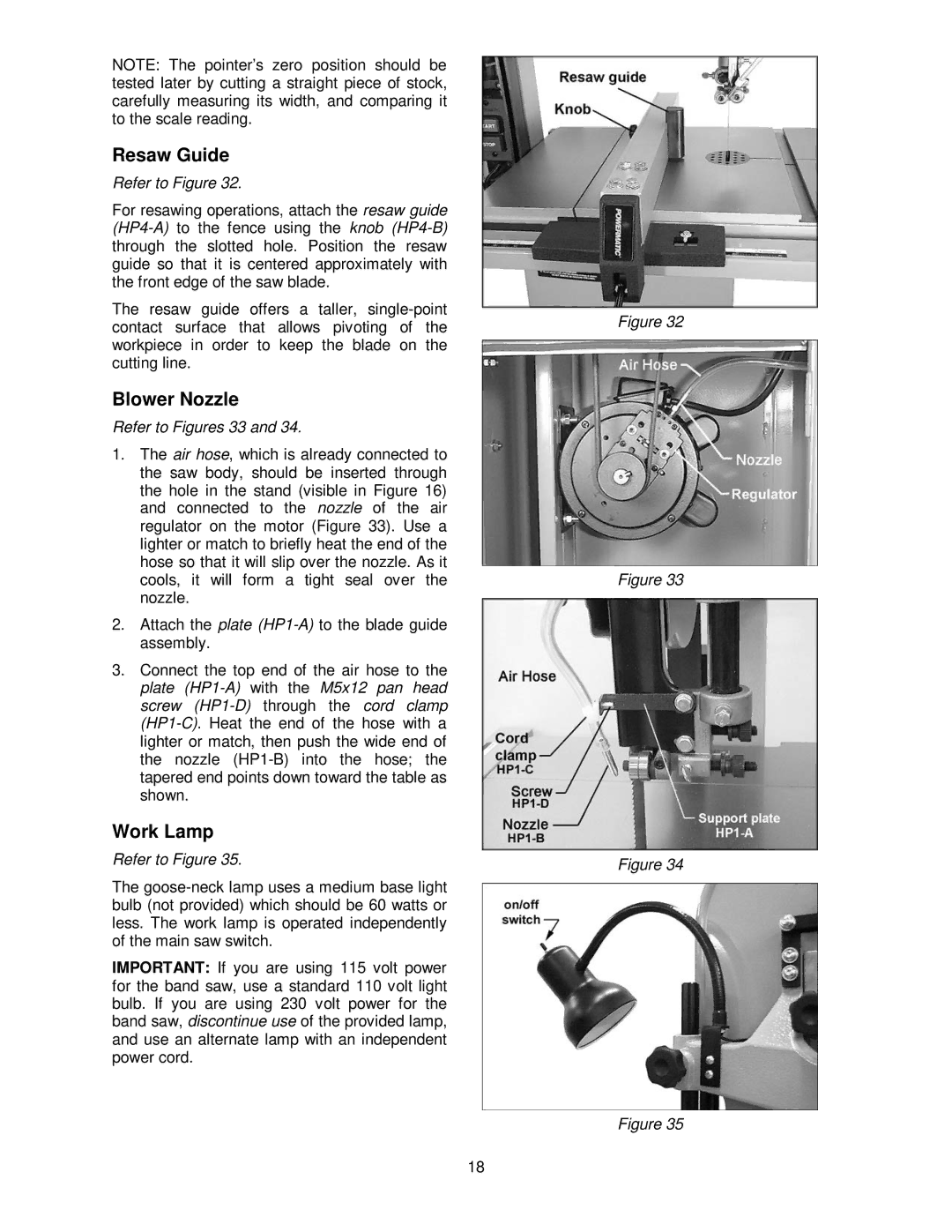
Refer to Figures 33 and 34.
1.The air hose, which is already connected to the saw body, should be inserted through the hole in the stand (visible in Figure 16) and connected to the nozzle of the air regulator on the motor (Figure 33). Use a lighter or match to briefly heat the end of the hose so that it will slip over the nozzle. As it cools, it will form a tight seal over the nozzle.
2.Attach the plate
3.Connect the top end of the air hose to the plate
Work Lamp
Refer to Figure 35.
The
IMPORTANT: If you are using 115 volt power for the band saw, use a standard 110 volt light bulb. If you are using 230 volt power for the band saw, discontinue use of the provided lamp, and use an alternate lamp with an independent power cord.
Figure 32
Figure 33
Figure 34
Figure 35
18