6.Remove the current blade from the upper wheel, then the lower wheel. Turn blade to direct it through the slot in the table.
![]() New blades are usually packaged in coiled position. Use gloves and grasp the coil with one hand while slowly uncoiling the blade with the other hand.
New blades are usually packaged in coiled position. Use gloves and grasp the coil with one hand while slowly uncoiling the blade with the other hand.
7.Guide new blade through table slot. Place blade in upper and lower blade guides, and around upper and lower wheels.
Note: Make sure blade teeth point forward and down toward the table. If the teeth won’t point downward no matter how you orient the blade, then the blade is twisted inside- out. Remove blade and, using gloves, twist it into correct orientation, then
8.Position blade so it lies on the center of both upper and lower wheels.
9.Raise tension lever to partial tension position.
10.
11.Tension and track the blade before operating saw. Proceed to "Blade Tension" and “Blade Tracking".
Blade Tension
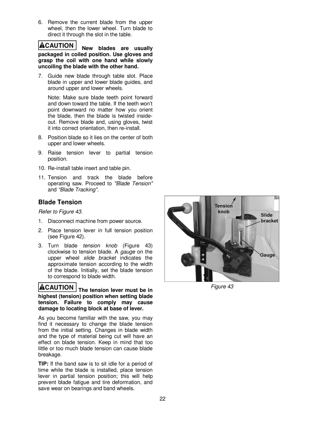
Refer to Figure 43.
1.Disconnect machine from power source.
2.Place tension lever in full tension position (see Figure 42).
3.Turn blade tension knob (Figure 43) clockwise to tension blade. A gauge on the upper wheel slide bracket indicates the approximate tension according to the width of the blade. Initially, set the blade tension to correspond to blade width.
The tension lever must be in | Figure 43 |
| |
highest (tension) position when setting blade |
|
tension. Failure to comply may cause |
|
damage to locating block at base of lever. |
|
As you become familiar with the saw, you may find it necessary to change the blade tension from the initial setting. Changes in blade width and the type of material being cut will have an effect on blade tension. Keep in mind that too little or too much blade tension can cause blade breakage.
TIP: If the band saw is to sit idle for a period of time while the blade is installed, place tension lever in partial tension position; this will help prevent blade fatigue and tire deformation, and save wear on bearings and band wheels.
22