Table Aligned with Blade
For accurate crosscuts using the miter gauge, the table (i.e. miter slot) must be aligned with the blade. This alignment has been set by the manufacturer, but the operator may wish to verify it, as follows. NOTE: This procedure works best with a wide blade.
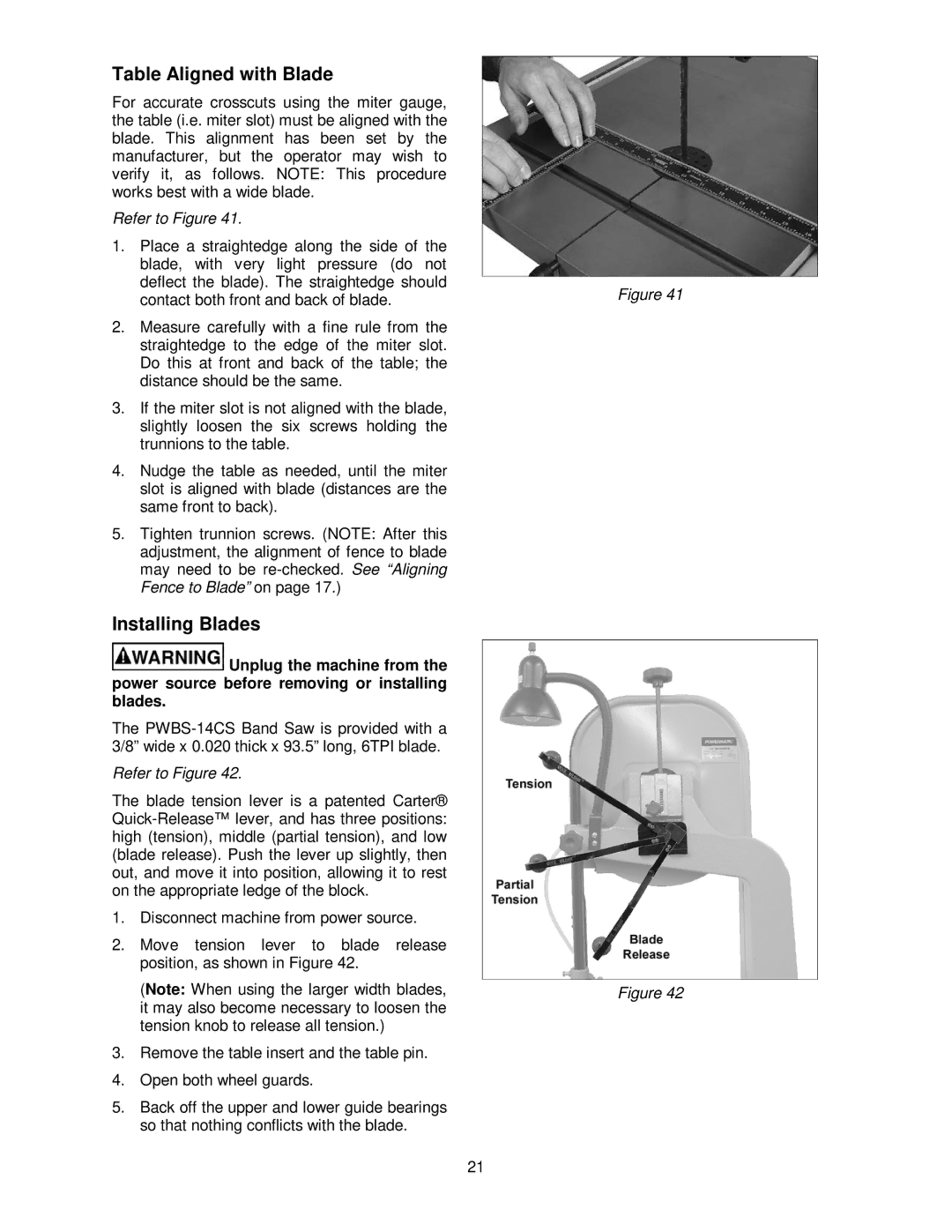
Refer to Figure 41.
1.Place a straightedge along the side of the blade, with very light pressure (do not deflect the blade). The straightedge should contact both front and back of blade.
2.Measure carefully with a fine rule from the straightedge to the edge of the miter slot. Do this at front and back of the table; the distance should be the same.
3.If the miter slot is not aligned with the blade, slightly loosen the six screws holding the trunnions to the table.
4.Nudge the table as needed, until the miter slot is aligned with blade (distances are the same front to back).
5.Tighten trunnion screws. (NOTE: After this adjustment, the alignment of fence to blade may need to be
Installing Blades
![]() Unplug the machine from the power source before removing or installing blades.
Unplug the machine from the power source before removing or installing blades.
The
Refer to Figure 42.
The blade tension lever is a patented Carter®
1.Disconnect machine from power source.
2.Move tension lever to blade release position, as shown in Figure 42.
(Note: When using the larger width blades, it may also become necessary to loosen the tension knob to release all tension.)
3.Remove the table insert and the table pin.
4.Open both wheel guards.
5.Back off the upper and lower guide bearings so that nothing conflicts with the blade.
Figure 41
Figure 42
21