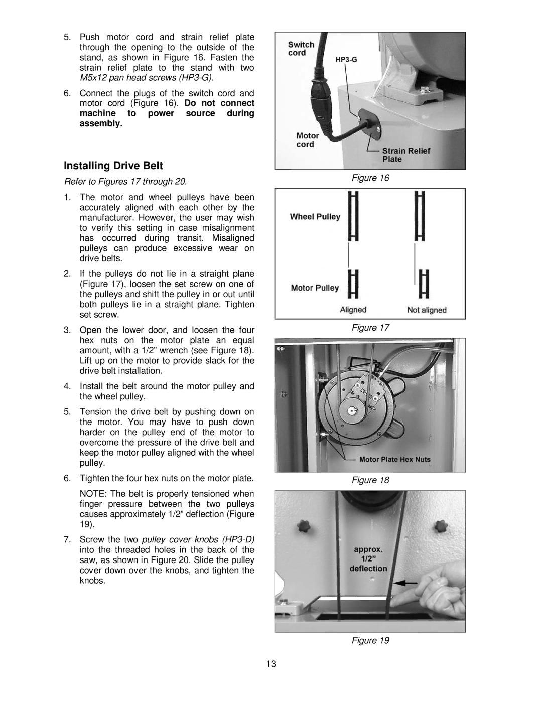
5.Push motor cord and strain relief plate through the opening to the outside of the stand, as shown in Figure 16. Fasten the strain relief plate to the stand with two M5x12 pan head screws
6.Connect the plugs of the switch cord and motor cord (Figure 16). Do not connect machine to power source during assembly.
Installing Drive Belt
Refer to Figures 17 through 20.
1.The motor and wheel pulleys have been accurately aligned with each other by the manufacturer. However, the user may wish to verify this setting in case misalignment has occurred during transit. Misaligned pulleys can produce excessive wear on drive belts.
2.If the pulleys do not lie in a straight plane (Figure 17), loosen the set screw on one of the pulleys and shift the pulley in or out until both pulleys lie in a straight plane. Tighten set screw.
3.Open the lower door, and loosen the four hex nuts on the motor plate an equal amount, with a 1/2” wrench (see Figure 18). Lift up on the motor to provide slack for the drive belt installation.
4.Install the belt around the motor pulley and the wheel pulley.
5.Tension the drive belt by pushing down on the motor. You may have to push down harder on the pulley end of the motor to overcome the pressure of the drive belt and keep the motor pulley aligned with the wheel pulley.
6.Tighten the four hex nuts on the motor plate.
NOTE: The belt is properly tensioned when finger pressure between the two pulleys causes approximately 1/2” deflection (Figure 19).
7.Screw the two pulley cover knobs
Figure 16
Figure 17
Figure 18
Figure 19
13