Black Box IC109A-R2, IC109C manual Simplified Functional Block Diagram DTE Operation, Installation

Models: IC109AE IC109A-R2 IC109C IC108C IC109A RS-232485/422 Converter Plus, RS-232485/422 Opto-Isolator/Converter IC108A IC108AE

1 33
Download 33 pages 8.26 Kb
Page 20
Image 20
Opto-isolated barrier

CHAPTER 3: Installation

Opto-isolated barrier

in IC109 models

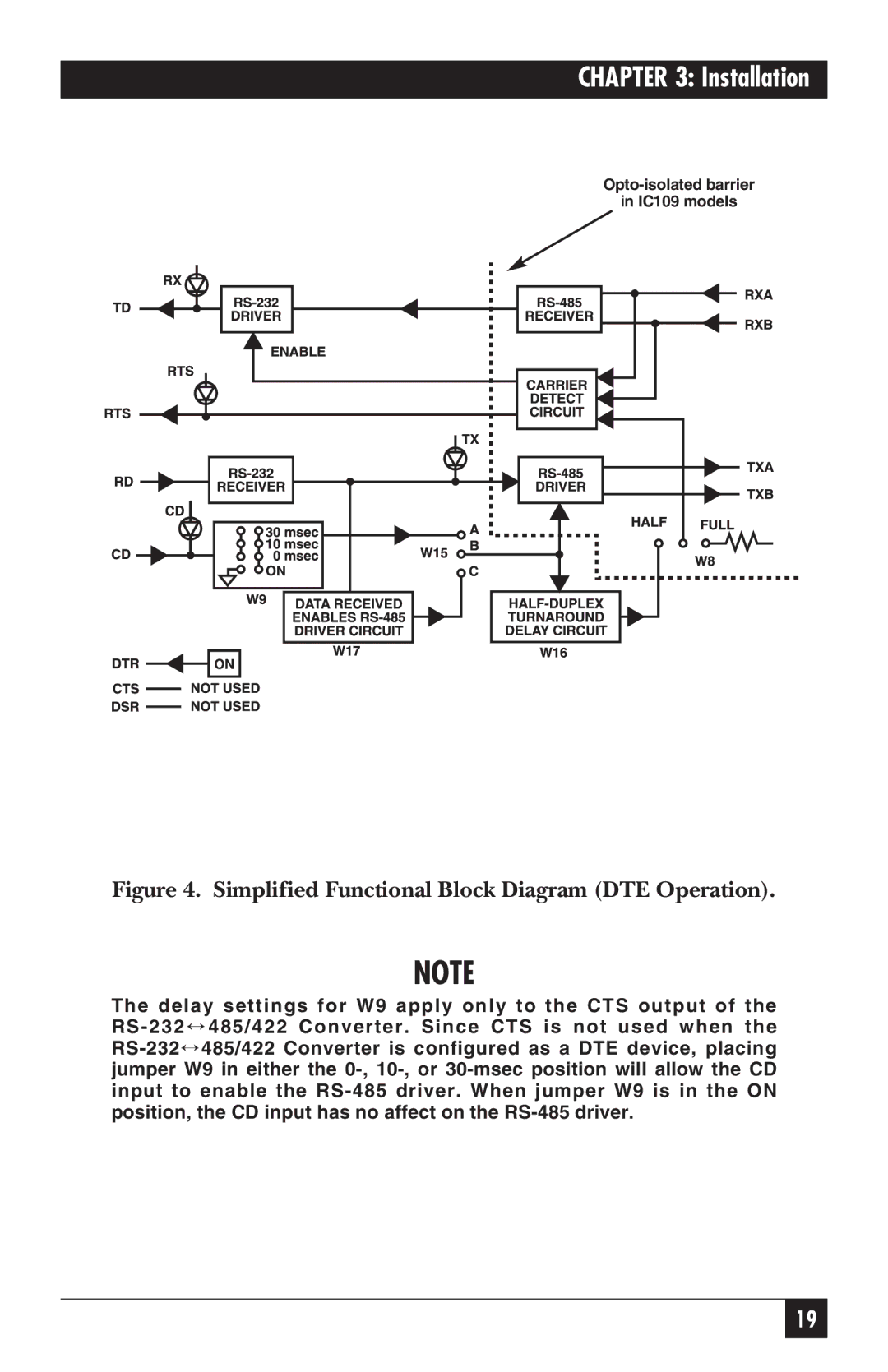
Figure 4. Simplified Functional Block Diagram (DTE Operation).

NOTE

The delay settings for W9 apply only to the CTS output of the RS-232485/422 Converter. Since CTS is not used when the RS-232485/422 Converter is configured as a DTE device, placing jumper W9 in either the 0-, 10-, or 30-msec position will allow the CD input to enable the RS-485 driver. When jumper W9 is in the ON position, the CD input has no affect on the RS-485 driver.

19

Page 20
Image 20
Black Box IC109A-R2 Simplified Functional Block Diagram DTE Operation, Installation, Opto-isolated barrier in IC109 models