Manuals
/
Black Box
/
Computer Equipment
/
Network Hardware
Black Box
IC109C, IC109AE, IC109A-R2, IC108C, IC108AE
manual
RS-232↔485/422 Converters
Models:
IC109AE
IC109A-R2
IC109C
IC108C
IC109A
RS-232485/422 Converter Plus, RS-232485/422 Opto-Isolator/Converter
IC108A
IC108AE
1
19
33
33
Download
33 pages
8.26 Kb
16
17
18
19
20
21
22
23
Specs
Install
Multipoint, 2-Wire Half-Duplex
DCE/DTE Configuration
DTE Jumper Settings
Driver Enabled by Data
Page 19
Image 19
RS-232
↔
485/422
CONVERTERS
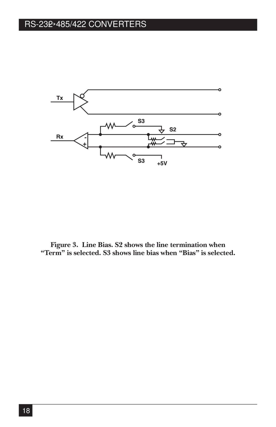
Figure 3. Line Bias. S2 shows the line termination when
“Term” is selected. S3 shows line bias when “Bias” is selected.
18
Page 18
Page 20
Page 19
Image 19
Page 18
Page 20
Contents
IC109AE
FCC and IC RFI Statements
RS-232↔485/422 Converters
NOM Statement
Trademarks Used in this Manual
Contents
Specifications
Specifications
Introduction
Jumper and Switch Configuration
Installation
Layout of the Printed Circuit Board
RS-232↔485/422 Converter as DCE XW1A 8-Position Shunt
Driver Enabled by Data
Point-to-Point
DCE/DTE Configuration
Function Jumper Requirements
RS-232↔485/422 Converters
Installation
RS-232↔485/422 Converters
Simplified Functional Block Diagram DTE Operation
DTE Jumper Settings
Installation
Typical Applications
Point-To-Point, 4-Wire Full- or Half-Duplex
Multipoint, 4-Wire Half- or Full-Duplex
Multipoint, 2-Wire Half-Duplex
Sample Multipoint Operation
Installation
DCE DTE
Appendix A. Pinning
Pin Name Description
XW1B
Quick Reference User-Selectable Options
Quick Reference USER-SELECTABLE Options
Copyright 2002. Black Box Corporation. All rights reserved
Top
Page
Image
Contents