| APPENDIX A: Pinning |
| Table 4. |
|
|
Pin Name | Description |
|
|
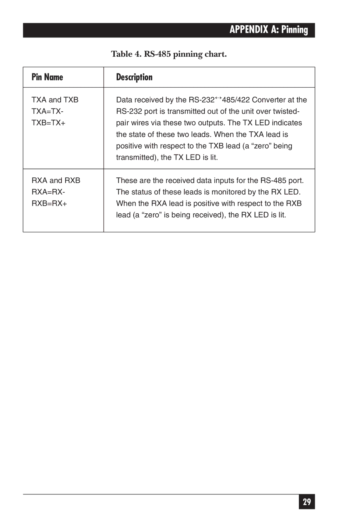
TXA and TXB | Data received by the |
TXA=TX- | |
TXB=TX+ | pair wires via these two outputs. The TX LED indicates |
| the state of these two leads. When the TXA lead is |
| positive with respect to the TXB lead (a “zero” being |
| transmitted), the TX LED is lit. |
|
|
RXA and RXB | These are the received data inputs for the |
RXA=RX- | The status of these leads is monitored by the RX LED. |
RXB=RX+ | When the RXA lead is positive with respect to the RXB |
| lead (a “zero” is being received), the RX LED is lit. |
|
|
29
