Galaxy 4000
CAUTION Isolate and
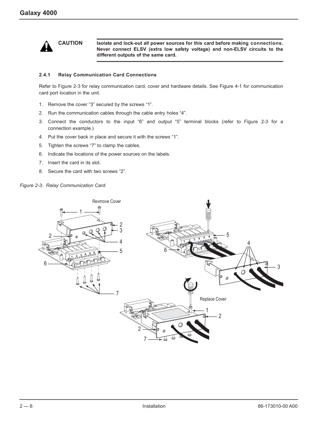
2.4.1Relay Communication Card Connections
Refer to Figure
1.Remove the cover “3” secured by the screws “1”.
2.Run the communication cables through the cable entry holes “4”.
3.Connect the conductors to the input “6” and output “5” terminal blocks (refer to Figure
4.Put the cover back in place and secure it with the screws “1”.
5.Tighten the screws “7” to clamp the cables.
6.Indicate the locations of the power sources on the labels.
7.Insert the card in its slot.
8.Secure the card with two screws “2”.
Figure 2-3: Relay Communication Card.
Revmove Cover
1
2
![]() 2
2 ![]() 3
3
|
|
| 3 | 4 | 5 | 6 | 5 |
4 | 1 | 2 |
| 4 |
BA
6
1 2 3 4 5 6 BA
56
7
Replace Cover
1
2
2
7
3
2 — 6 | Installation |