2. Installation
2.5 Connections
Check that the indications on the rating plate on the back of the UPS correspond to your
Tower model |
|
|
|
|
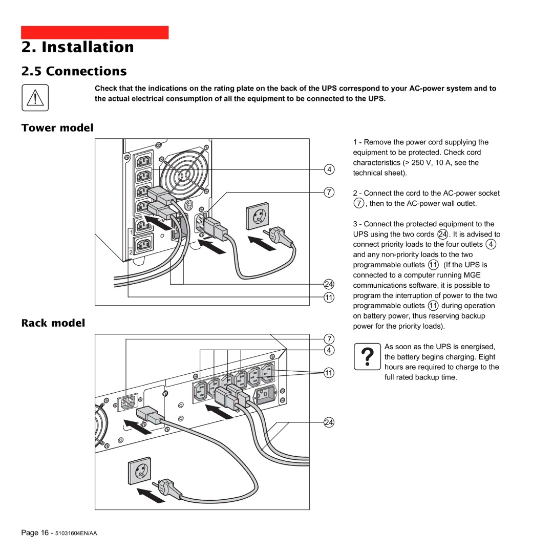
| 1 - Remove the power cord supplying the | |
|
| equipment to be protected. Check cord | |
| 4 | characteristics (> 250 V, 10 A, see the | |
| technical sheet). |
| |
|
|
| |
?r | 7 | 2 - Connect the cord to the | |
| Ê Ê 7 , then to the | ||
ress |
|
|
|
p |
|
|
|
tese |
|
|
|
|
| 3 - Connect the protected equipment to the | |
1 |
| UPS using the two cords | 24 . It is advised to |
|
| connect priority loads to the four outlets 4 | |
2 |
| and any | |
|
| programmable outlets 11 | (If the UPS is |
|
| connected to a computer running MGE | |
| 24 | communications software, it is possible to | |
| 11 | program the interruption of power to the two | |
|
| programmable outlets 11 | during operation |
Rack model |
| on battery power, thus reserving backup | |
| power for the priority loads). | ||
| 7 | As soon as the UPS is energised, | |
| 4 | ||
| the battery begins charging. Eight | ||
|
| ||
| 2 | hours are required to charge to the | |
1 | 11 |
|
|
| full rated backup time. | ||
|
| ||
| 24 |
|
|
Page 16 - 51031604EN/AA |
|
|
|
