PV-5127A, PV-5127 specifications
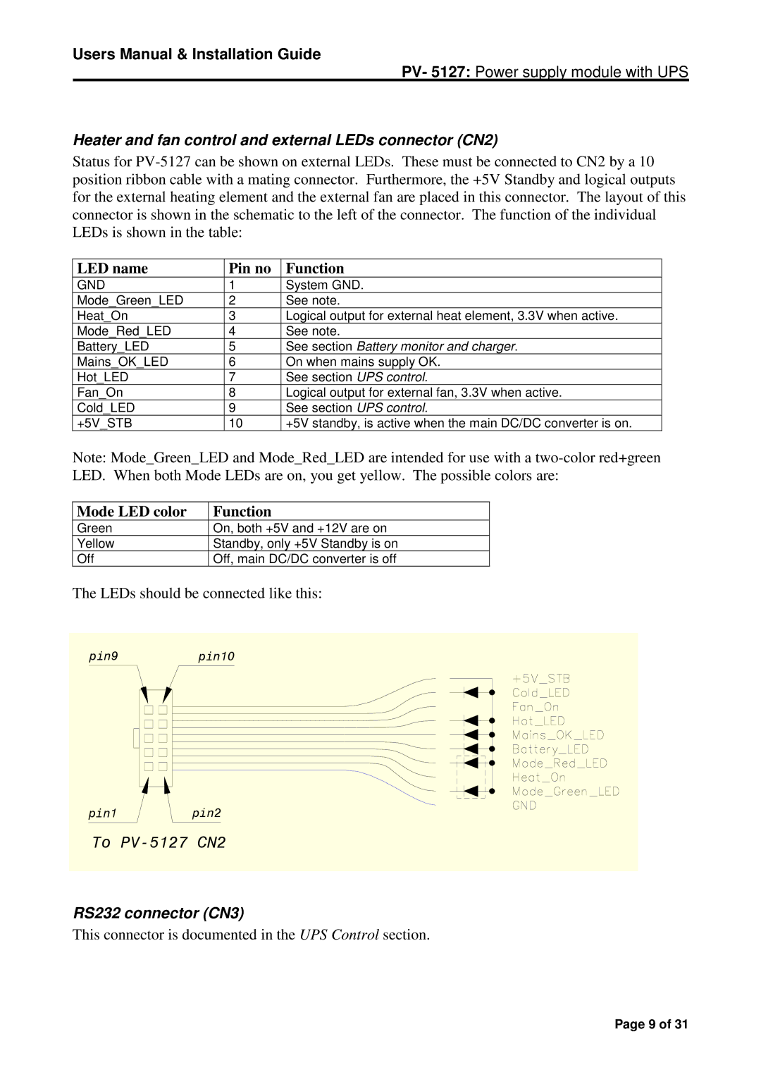
The Micro Technic PV-5127 and PV-5127A models represent a significant achievement in the field of precision measurement instruments, specifically designed to enhance efficiency and accuracy in various industrial and scientific applications. These devices are characterized by their robust construction, user-friendly interface, and advanced technological features that cater to the needs of professionals.One of the standout features of both the PV-5127 and PV-5127A is their high-resolution digital display, which provides clear readouts of measurements, ensuring that users can easily interpret data in real time. The devices boast a wide measurement range, allowing them to perform accurate readings across various parameters, including voltage, current, and resistance. This versatility makes them ideal for use in labs, research facilities, and fieldwork.
The PV-5127 and PV-5127A incorporate advanced microprocessor technology, ensuring precise measurements and quick response times. This technology enhances the instrument's ability to perform complex calculations, making it suitable for various applications, including electronics testing, industrial maintenance, and educational purposes.
Both models feature intuitive controls, enabling users to navigate functions effortlessly. The user interface is designed for simplicity, minimizing the learning curve for new users while empowering seasoned professionals to utilize the instruments to their full potential. Additionally, the PV-5127A includes enhanced features such as data logging and connectivity options, allowing users to transfer data to computers or other devices for further analysis.
Durability is another notable characteristic of these models. Constructed to withstand harsh working conditions, the PV-5127 and PV-5127A are built with high-quality materials that protect against impacts and environmental factors, ensuring longevity and reliability.
Power efficiency is also a critical aspect, as both models offer low power consumption without compromising performance. This feature is particularly important for users who rely on portable devices for extended periods.
In summary, the Micro Technic PV-5127 and PV-5127A models are sophisticated measurement instruments that combine advanced technology with user-friendly design. Their versatility, durability, and efficiency make them valuable tools for professionals across various fields, enhancing productivity and accuracy in measurement tasks. Whether in a laboratory setting or an industrial environment, these devices stand out as reliable companions for precise measurements.

