TRANSCEIVER OPERATION (Continued)
1.Set-up Tab
This screen is used to set the PC Serial Port to interface with the MiniLink Data 900 or 2400 MHz Transceiver. The parameters in this tab must match the PC Serial Port Parameters for communication to be established.
2.Com Test Tab
This screen is used to test the MiniLink Data transceiver and monitor communications once the two transceivers are both set to match the parameters of your system.
Running a Com Test: (See Notes and instructions on the CTU Software below before testing)
1.Two Data transceivers must be in
2.One transceiver must be connected to a PC or laptop using the
3.Click on the “Com Test” tab & click “Start”. Test results should appear on the screen (Either “Good” or “bad”). You can click “Stop” when you like. Click “Clear Results” and switch the units to make sure they pass the test as a transmitter and as a receiver.
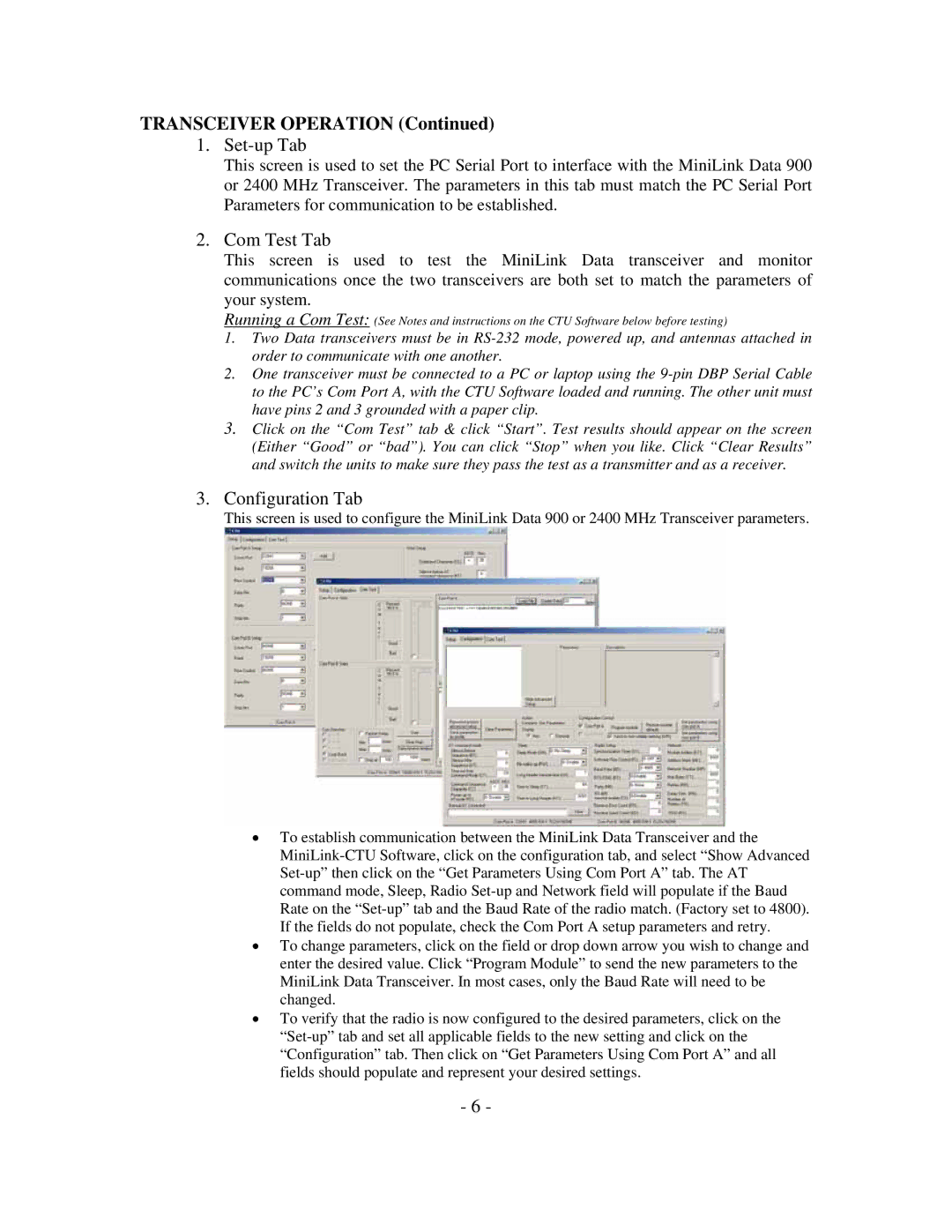
3.Configuration Tab
This screen is used to configure the MiniLink Data 900 or 2400 MHz Transceiver parameters.
•To establish communication between the MiniLink Data Transceiver and the
•To change parameters, click on the field or drop down arrow you wish to change and enter the desired value. Click “Program Module” to send the new parameters to the MiniLink Data Transceiver. In most cases, only the Baud Rate will need to be changed.
•To verify that the radio is now configured to the desired parameters, click on the
- 6 -