III. ASSEMBLY
SECTION 2 - INSTALLATION
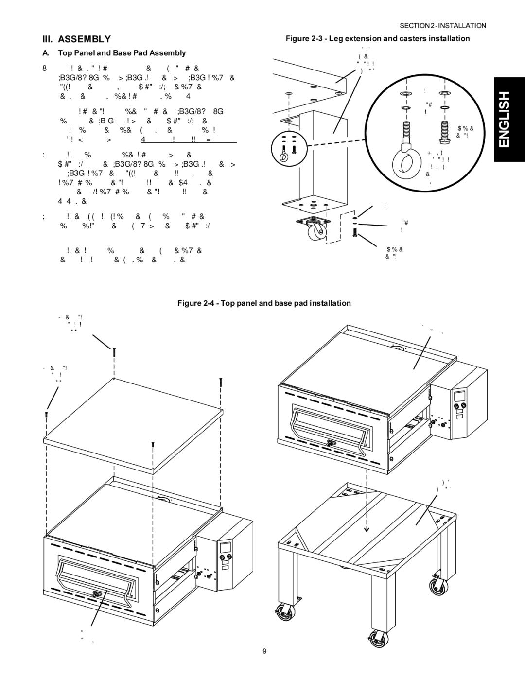
Figure 2-3 - Leg extension and casters installation
A.Top Panel and Base Pad Assembly
1.Install the four leg extensions onto the base pad using the
One rear leg should be attached using three
2.Install one caster onto each leg extension, as shown in Figure
3.Install the top panel in place on the top oven cavity using the screws included in the base pad kit, as shown in Figure 2- 4.
4.Install the lower oven cavity onto the base pad. Check that the eyebolt welded onto the pad faces the rear of the oven.
Locking casters - FRONT of oven
Non-locking casters -
REAR of oven
Finished sides of
leg extension face corner of base pad
3/8" flat washer
3/8" lock
washer
![]()
![]() hex screw
hex screw
3/4" eyebolt (inside corner of one rear leg extension only)
3/8" flat washer
3/8" lock
washer
ENGLISH
#10 x 2" screws
attach rear of
top panel
#10 x 1" screws attach front of top panel
Top oven
cavity
Figure 2-4 - Top panel and base pad installation
Bottom oven
cavity
Assembled
base pad
9