ENGLISH
SECTION 2 - INSTALLATION
6.Lift the conveyor and position it in the oven. The conveyor can only be installed from the end of the oven with the drive motor.
7.Continue moving the conveyor into the oven until the con- veyor frame is positioned properly. The inside supports for the crumb trays should rest firmly against the lower end plugs, as shown in Figure
8.When the conveyor is positioned properly, check for free- dom of movement of the conveyor belt by pulling it for about
9.Install the drive chain between the conveyor drive sprocket and the motor sprocket. To install the chain, it will be necessary to lift the drive end of the conveyor slightly.
V. FINAL ASSEMBLY
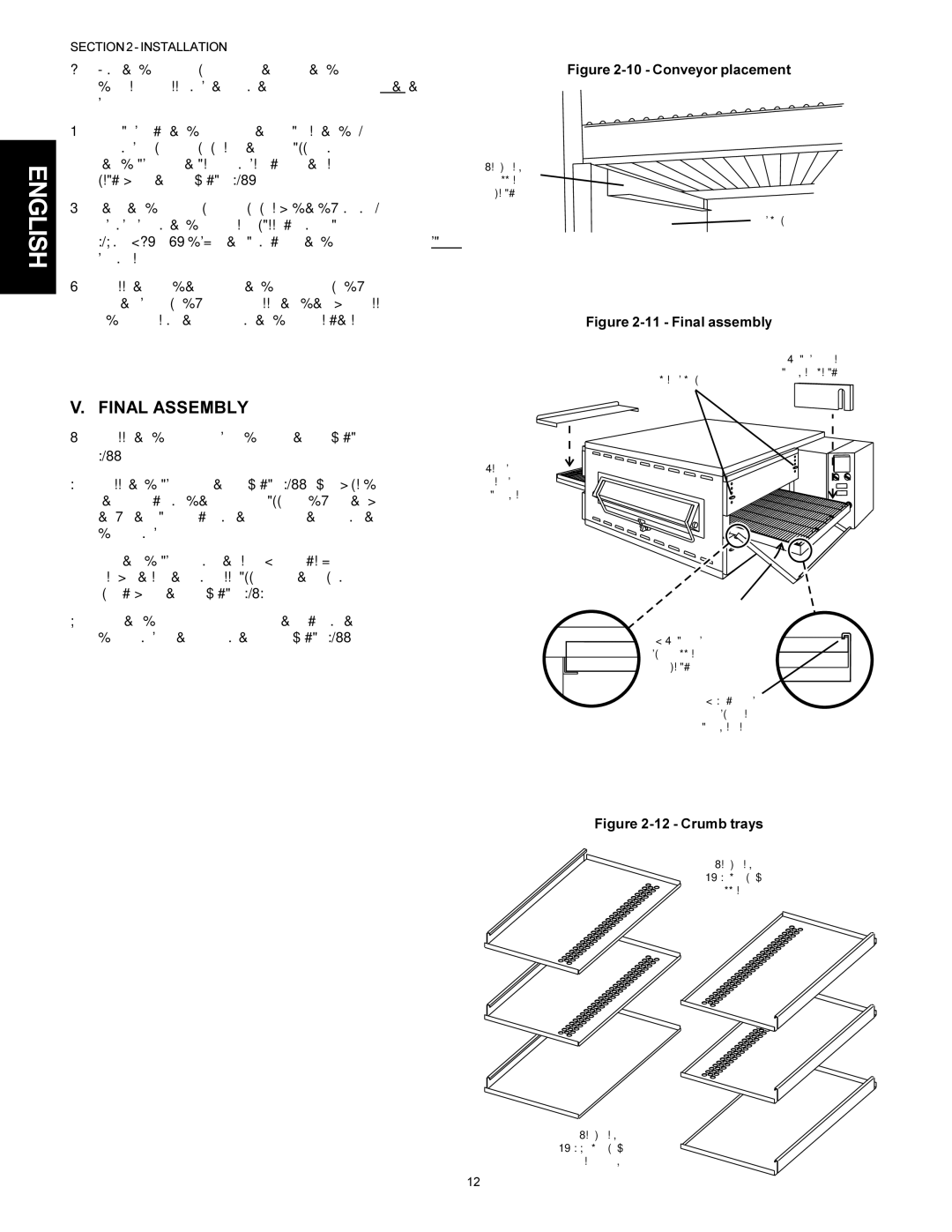
1.Install the conveyor drive motor cover as shown in Figure
2.Install the crumb trays as shown in Figure
Note that crumb trays for the lower (or a single) oven are solid, while those for all upper ovens have perforated openings, as shown in Figure
3.Press the conveyor exit tray down over the edge of the conveyor frame at the exit end of the oven. See Figure
Figure 2-10 - Conveyor placement
Crumb tray
support bracket
End plug
Figure 2-11 - Final assembly
Chain cover:
Place down over
Wing screwsconveyor sprocket 2 per end plug
Conveyor exit tray:
Press down over end of conveyor
Crumb trays (2):
1. Place inside edge on support bracket
2. Hook outside
edge over
conveyor frame
Figure 2-12 - Crumb trays
Crumb trays
WITH openings - all upper ovens
Crumb trays
WITHOUT openings -
lower oven only
12