SECTION 4
MAINTENANCE
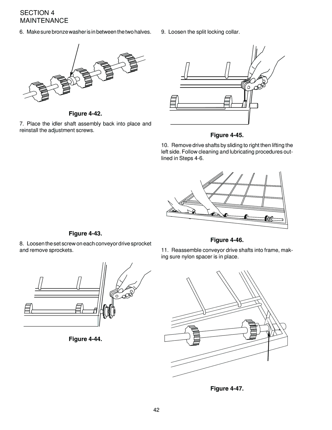
6. Make sure bronze washer is in between the two halves. | 9. Loosen the split locking collar. | ||||||||||||||||
|
|
|
|
|
|
|
|
|
|
|
|
|
|
|
|
|
|
|
|
|
|
|
|
|
|
|
|
|
|
|
|
|
|
|
|
|
|
|
|
|
|
|
|
|
|
|
|
|
|
|
|
|
|
|
|
|
|
|
|
|
|
|
|
|
|
|
|
|
|
|
|
|
|
|
|
|
|
|
|
|
|
|
|
|
|
|
|
|
|
|
|
|
|
|
|
|
|
|
|
|
|
|
|
|
|
|
|
|
|
|
|
|
|
|
|
|
|
|
|
|
|
|
|
|
|
|
|
|
|
|
|
|
|
|
|
|
|
|
|
|
|
|
|
|
|
|
|
|
|
|
|
|
|
|
|
|
|
|
|
|
|
|
|
|
|
|
|
|
|
|
|
|
|
|
|
|
|
|
|
|
|
|
|
|
|
|
|
|
|
|
|
|
|
|
|
|
|
|
|
|
|
|
|
|
|
|
|
|
|
|
|
|
|
|
|
|
|
|
|
|
|
|
|
|
|
|
|
|
|
|
|
|
|
|
|
|
|
|
|
|
|
|
|
|
|
|
|
|
|
|
|
Figure
7.Place the idler shaft assembly back into place and reinstall the adjustment screws.
Figure
8.Loosen the set screw on each conveyor drive sprocket and remove sprockets.
Figure
Figure
10.Remove drive shafts by sliding to right then lifting the left side. Follow cleaning and lubricating procedures out- lined in Steps
Figure
11.Reassemble conveyor drive shafts into frame, mak- ing sure nylon spacer is in place.
Figure
42
