Figure 3-2. Attach mounting brackets with screws
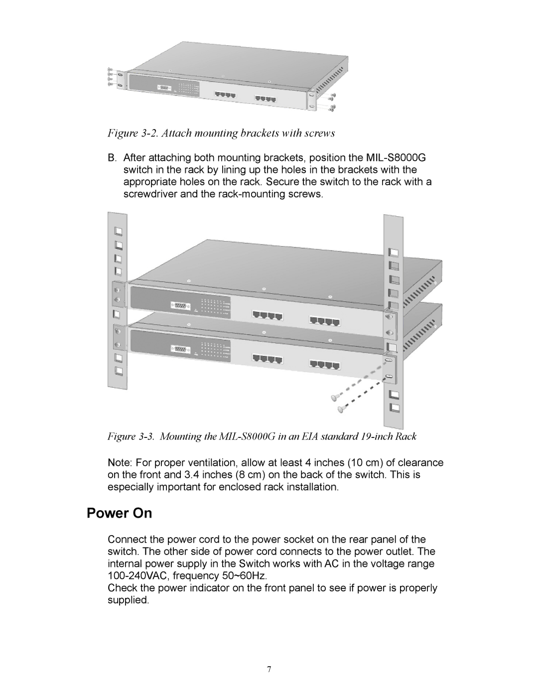
B.After attaching both mounting brackets, position the
Figure 3-3. Mounting the MIL-S8000G in an EIA standard 19-inch Rack
Note: For proper ventilation, allow at least 4 inches (10 cm) of clearance on the front and 3.4 inches (8 cm) on the back of the switch. This is especially important for enclosed rack installation.
Power On
Connect the power cord to the power socket on the rear panel of the switch. The other side of power cord connects to the power outlet. The internal power supply in the Switch works with AC in the voltage range
Check the power indicator on the front panel to see if power is properly supplied.
7