OUT Timing Source
OUTPUTS SYNC
A IN
INPUTS
L 1 R | L 2 R | L 3 R | L 4 R |
B | OUT |
| SW 4AV Rear Panel |
| To next device |
IN | or terminate. |
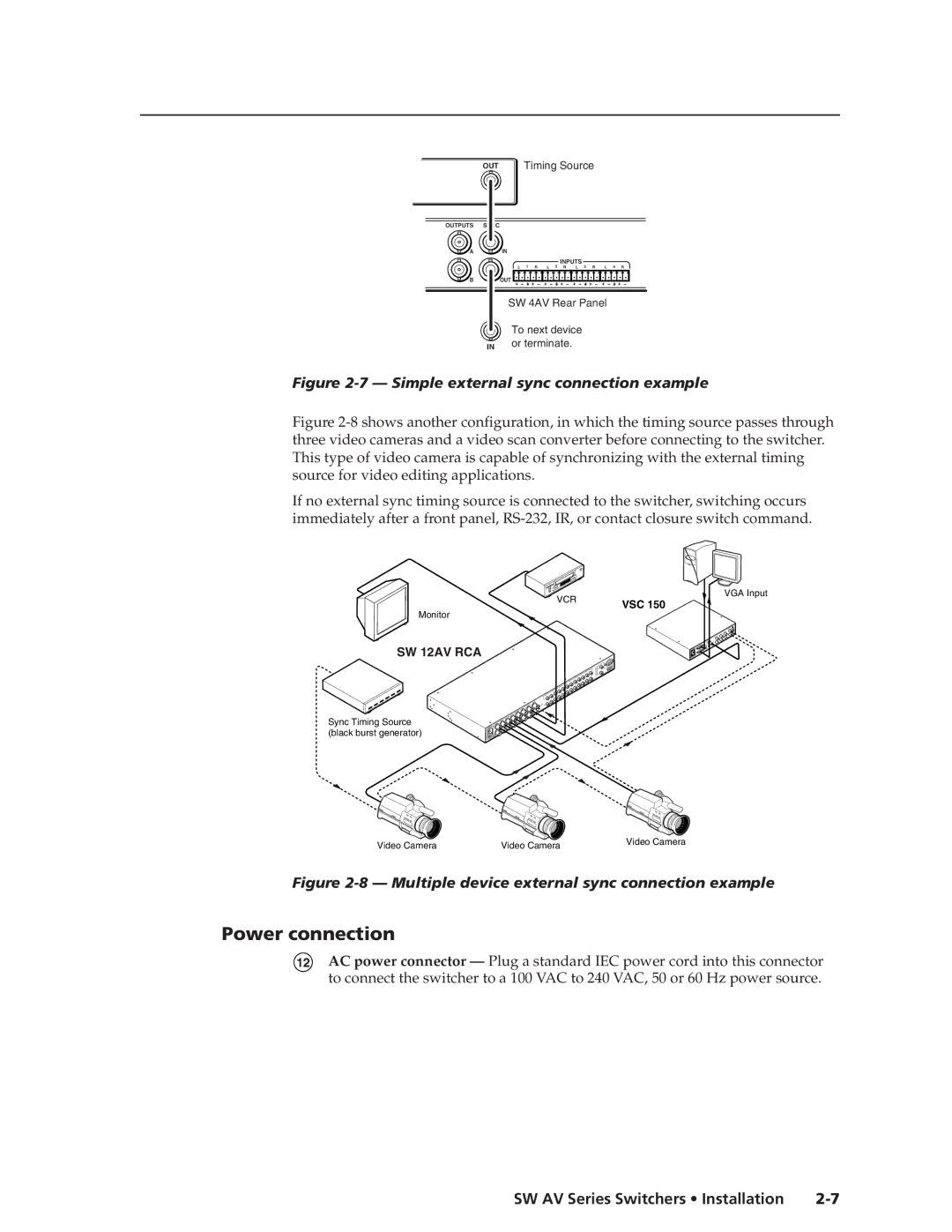
Figure 2-7 — Simple external sync connection example
Figure 2-8 shows another configuration, in which the timing source passes through three video cameras and a video scan converter before connecting to the switcher. This type of video camera is capable of synchronizing with the external timing source for video editing applications.
If no external sync timing source is connected to the switcher, switching occurs immediately after a front panel, RS-232, IR, or contact closure switch command.
VCR | VGA Input | |
VSC 150 | ||
|
Monitor
SW 12AV RCA
Sync Timing Source (black burst generator)
12AVSWRCA | R |
| L |
L |
R |
Video Camera | Video Camera | Video Camera |
|
Figure 2-8 — Multiple device external sync connection example
Power connection
12AC power connector — Plug a standard IEC power cord into this connector to connect the switcher to a 100 VAC to 240 VAC, 50 or 60 Hz power source.
