Installation, cont’d
1 | 3 | 10 | 9 |
|
12 | 3 | 11 | 5 | 7 |
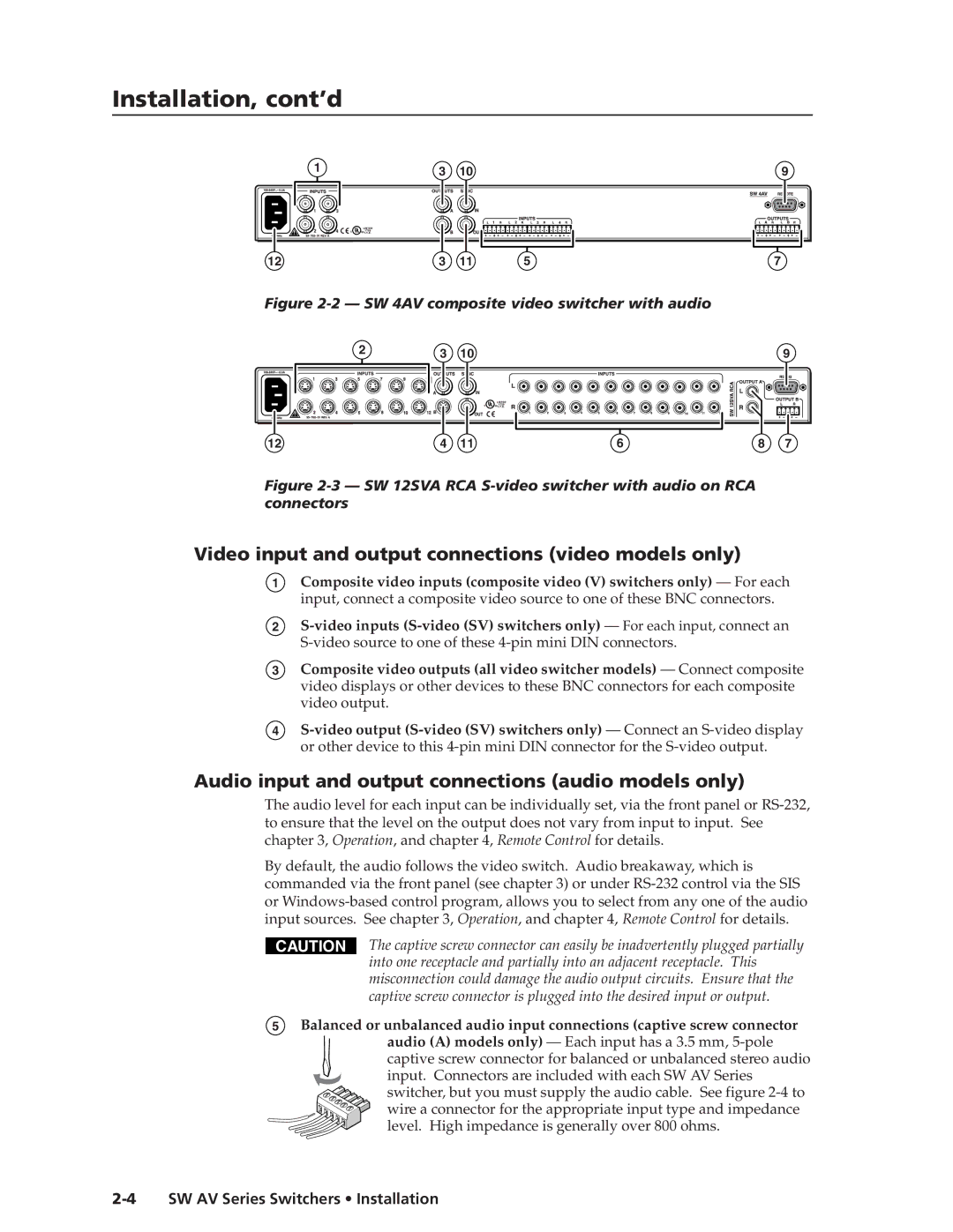
Figure 2-2 — SW 4AV composite video switcher with audio
2 | 3 | 10 | 9 |
|
12 | 4 | 11 | 6 | 8 | 7 |
Figure 2-3 — SW 12SVA RCA S-video switcher with audio on RCA connectors
Video input and output connections (video models only)
1Composite video inputs (composite video (V) switchers only) — For each input, connect a composite video source to one of these BNC connectors.
2
3
4
Composite video outputs (all video switcher models) — Connect composite video displays or other devices to these BNC connectors for each composite video output.
Audio input and output connections (audio models only)
The audio level for each input can be individually set, via the front panel or
By default, the audio follows the video switch. Audio breakaway, which is commanded via the front panel (see chapter 3) or under
CAUTION
The captive screw connector can easily be inadvertently plugged partially into one receptacle and partially into an adjacent receptacle. This misconnection could damage the audio output circuits. Ensure that the captive screw connector is plugged into the desired input or output.
5Balanced or unbalanced audio input connections (captive screw connector audio (A) models only) — Each input has a 3.5 mm,
captive screw connector for balanced or unbalanced stereo audio input. Connectors are included with each SW AV Series switcher, but you must supply the audio cable. See figure