Extron electronic SW AV manual Cabling and Rear Panel Views, 1 - Mounting the switcher

Models: SW AV

1 50
Download 50 pages 17.64 Kb
Page 15
Image 15
Figure 2-1 — Mounting the switcher

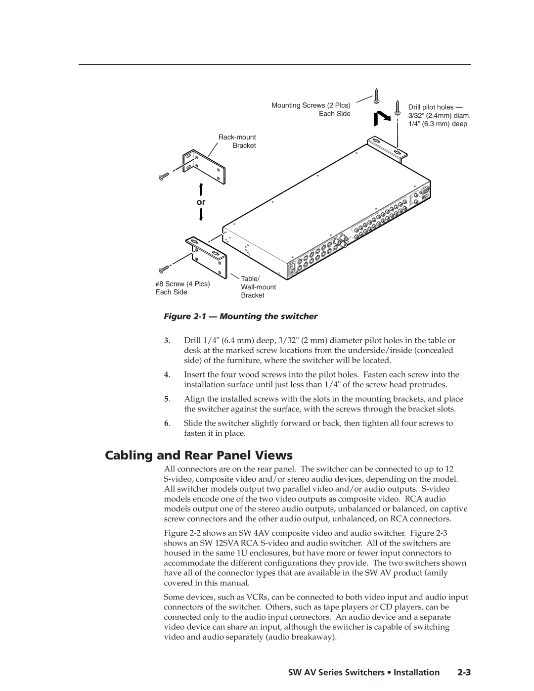
Mounting Screws (2 Plcs)

Each Side

Rack-mount

Bracket

Drill pilot holes — 3/32” (2.4mm) diam. 1/4” (6.3 mm) deep

or

SYNC


TPU

TS


OU


11


9


A


PUTS

7


IN


12

B


5


3


10


1


8


6


4


2


#8 Screw (4 Plcs)

Table/

Wall-mount

Each Side

Bracket


L Cabling and Rear Panel Views

SW AV Series Switchers • Installation 2-3Manual background2

1 R

3

3


INPU

TS


9


8


7

5


6

4

5


4


SW12SVARCA


11

10

12


11

10


RS

232


UT

A

T B

OUT

P


TPU R

L


OUL


R


Figure 2-1 — Mounting the switcher

3.

Drill 1/4" (6.4 mm) deep, 3/32" (2 mm) diameter pilot holes in the table or


desk at the marked screw locations from the underside/inside (concealed


side) of the furniture, where the switcher will be located.

4.

Insert the four wood screws into the pilot holes. Fasten each screw into the


installation surface until just less than 1/4" of the screw head protrudes.

5.

Align the installed screws with the slots in the mounting brackets, and place


the switcher against the surface, with the screws through the bracket slots.

6.

Slide the switcher slightly forward or back, then tighten all four screws to


fasten it in place.

Cabling and Rear Panel Views

All connectors are on the rear panel. The switcher can be connected to up to 12 S-video, composite video and/or stereo audio devices, depending on the model. All switcher models output two parallel video and/or audio outputs. S-video models encode one of the two video outputs as composite video. RCA audio models output one of the stereo audio outputs, unbalanced or balanced, on captive screw connectors and the other audio output, unbalanced, on RCA connectors.

Figure 2-2 shows an SW 4AV composite video and audio switcher. Figure 2-3 shows an SW 12SVA RCA S-video and audio switcher. All of the switchers are housed in the same 1U enclosures, but have more or fewer input connectors to accommodate the different configurations they provide. The two switchers shown have all of the connector types that are available in the SW AV product family covered in this manual.

Some devices, such as VCRs, can be connected to both video input and audio input connectors of the switcher. Others, such as tape players or CD players, can be connected only to the audio input connectors. An audio device and a separate video device can share an input, although the switcher is capable of switching video and audio separately (audio breakaway).

SW AV Series Switchers • Installation 2-3

Page 15
Image 15
Extron electronic manual Cabling and Rear Panel Views, 1 - Mounting the switcher, SW AV Series Switchers Installation