Specifications, cont’d
Control/remote — switcher
Serial control port | |
| input models) |
Baud rate and protocol | 9600 baud, 8 data bits, 1 stop bit, no parity |
Serial control pin configurations | 2 = TX, 3 = RX, 5 = GND |
Contact closure (SW 4/6 ___) .... | (1) |
Contact closure pin configurations (SW 4/6 ___ models only) | |
| 1 = input 1, 4 = input 2, 5 = GND, 6 = input 3, 7 = input 4, 8 = input 5, 9 = |
| input 6 |
IR controller module | Extron IR 102 kit (optional) |
Program control | Extron’s control/configuration program for Windows® |
| Extron’s Simple Instruction Set (SIS™) |
General
Power | 100 VAC to 240VAC, 50/60 Hz, 20 watts, internal, autoswitchable | ||
Temperature/humidity | .............. Storage: | ||
|
| Operating: +32 to +122 °F (0 to +50 °C) / 10% to 90%, noncondensing | |
Rack mount | Yes, with included brackets, part |
| |
|
| Also |
|
Enclosure type | Metal |
| |
Enclosure dimensions | 1.75" H x 17.4" W x 8.5" D (1U high, full rack wide) |
| |
|
| 4.4 cm H x 44.2 cm W x 21.6 cm D |
|
|
| (Depth excludes connectors.) |
|
Product weight | 7.0 lbs (3.2 kg) |
| |
Shipping weight | 10 lbs (5 kg) |
| |
Vibration | ISTA 1A in carton (International Safe Transit Association) |
| |
Listings | UL, CUL |
| |
Compliances | CE, FCC Class A, VCCI, AS/NZS, ICES |
| |
MTBF | 30,000 hours |
| |
Warranty | 3 years parts and labor |
| |
| All nominal levels are at ±10% |
| |
|
| ||
| Specifications are subject to change without notice. |
| |
|
| ||
Part Numbers |
| ||
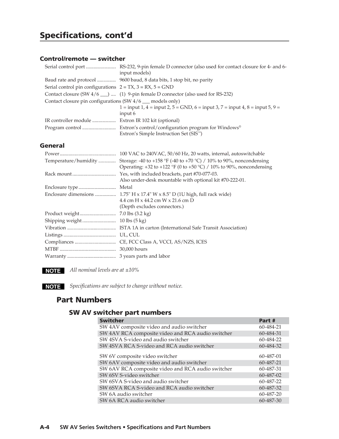
| SW AV switcher part numbers |
| |
|
|
|
|
|
| Switcher | Part # |
|
| SW 4AV composite video and audio switcher | |
|
| SW 4AV RCA composite video and RCA audio switcher | |
|
| SW 4SVA | |
|
| SW 4SVA RCA | |
|
| SW 6V composite video switcher | |
|
|
|
|
|
| SW 6AV composite video and audio switcher | |
|
| SW 6AV RCA composite video and RCA audio switcher | |
|
| SW 6SV | |
|
| SW 6SVA | |
|
| SW 6SVA RCA | |
|
| SW 6A audio switcher | |
|
| SW 6A RCA audio switcher | |