•Audio switcher — Switches audio on captive screw or RCA connectors. May or may not include video switching.
•
•Video AND audio switcher — Switches both composite video or
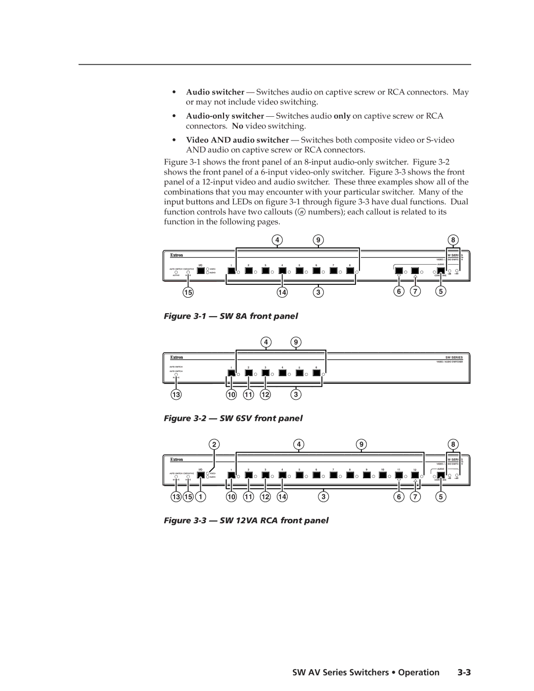
Figure 3-1 shows the front panel of an 8-input audio-only switcher. Figure 3-2 shows the front panel of a 6-input video-only switcher. Figure 3-3 shows the front panel of a 12-input video and audio switcher. These three examples show all of the combinations that you may encounter with your particular switcher. Many of the input buttons and LEDs on figure 3-1 through figure 3-3 have dual functions. Dual function controls have two callouts ( n numbers); each callout is related to its function in the following pages.
4 | 9 | 8 |
SW SERIES
VIDEO / AUDIO SWITCHER
I/O | 1 | 2 | 3 | 4 | 5 | 6 | 7 | 8 | AUDIO |
AUTO SWITCH EXECUTIVE | VIDEO |
|
| |
|
| AUDIO | +dB | |
ACTIVE | MODE |
| CONF/SAVE |
|
15 | 14 | 3 | 6 | 7 | 5 |
Figure 3-1 — SW 8A front panel
|
|
| 4 |
| 9 |
|
AUTO SWITCH | 1 | 2 | 3 | 4 | 5 | 6 |
| ||||||
AUTO SWITCH |
|
|
|
|
|
|
ACTIVE |
|
|
|
|
|
|
13 | 10 | 11 | 12 |
| 3 |
|
Figure 3-2 — SW 6SV front panel
SW SERIES
VIDEO / AUDIO SWITCHER
2 |
|
|
|
| 4 |
|
|
| 9 |
|
|
| 8 |
|
|
|
|
|
|
|
|
|
|
|
|
| SW SERIES |
|
|
|
|
|
|
|
|
|
|
|
|
| VIDEO / AUDIO SWITCHER |
I/O | 1 | 2 | 3 | 4 | 5 | 6 | 7 | 8 | 9 | 10 | 11 | 12 | AUDIO |
AUTO SWITCH EXECUTIVE | VIDEO |
|
|
| AUDIO | +dB |
ACTIVE | MODE | CONF/SAVE |
13 | 15 | 1 | 10 | 11 | 12 | 14 | 3 | 6 | 7 | 5 |