RemoteControl,cont’d
The SW AV Series switchers can be remotely controlled via the switcher’s rear panel Remote (SW 4 and SW 6 models) or
•A host device such as a computer or
•A device such as an Extron IR 102 Universal remote control kit
•A contact closure device such as an Extron KP 6 Keypad Control
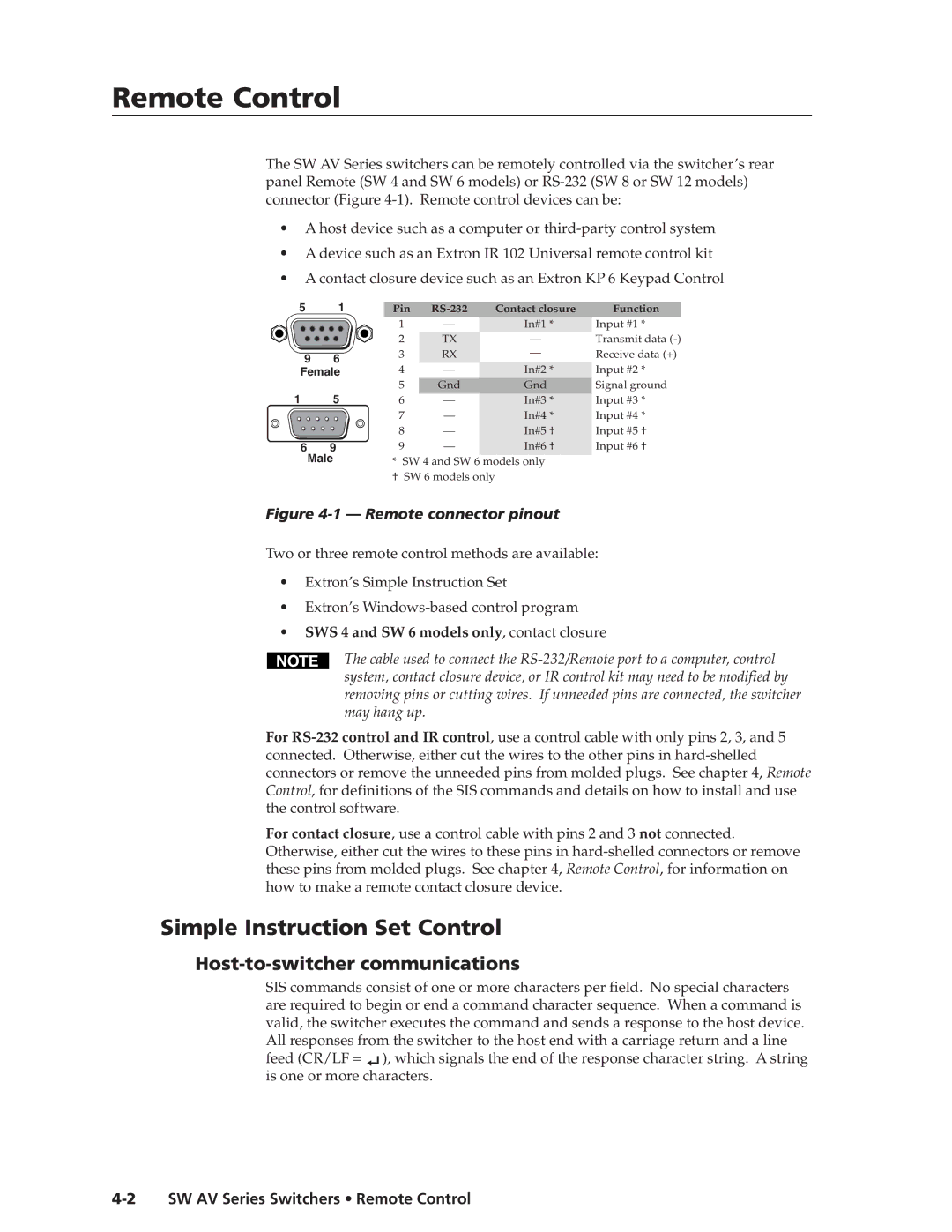
5 | 1 | Pin | Contact closure | Function | ||
|
| 1 | — | In#1 * | Input #1 * | |
|
| 2 | TX | — | Transmit data | |
9 | 6 | 3 | RX | — | Receive data (+) | |
4 | — | In#2 * | Input #2 * | |||
Female | ||||||
|
| 5 | Gnd | Gnd | Signal ground | |
1 | 5 | 6 | — | In#3 * | Input #3 * | |
|
| 7 | — | In#4 * | Input #4 * | |
|
| 8 | — | In#5 † | Input #5 † | |
6 | 9 | 9 | — | In#6 † | Input #6 † | |
Male | * SW 4 and SW 6 models only |
| ||||
† SW 6 models only
Figure 4-1 — Remote connector pinout
Two or three remote control methods are available:
•Extron’s Simple Instruction Set
•Extron’s
•SWS 4 and SW 6 models only, contact closure
The cable used to connect the
For
For contact closure, use a control cable with pins 2 and 3 not connected. Otherwise, either cut the wires to these pins in
Simple Instruction Set Control
Host-to-switcher communications
SIS commands consist of one or more characters per field. No special characters are required to begin or end a command character sequence. When a command is valid, the switcher executes the command and sends a response to the host device. All responses from the switcher to the host end with a carriage return and a line feed (CR/LF = ![]() ), which signals the end of the response character string. A string is one or more characters.
), which signals the end of the response character string. A string is one or more characters.