| ||||||
|
|
|
| 9 | Pin | Pin Information |
|
|
|
|
|
| |
|
|
|
|
| A | Capacitor C1 to ground |
|
|
|
|
| B | Shield |
|
|
| F |
| C | Volt sense |
|
|
| G | D | Can low | |
| E |
|
| |||
|
|
| H | |||
|
|
|
|
| ||
|
|
|
| E | Can high | |
| D |
| I |
| ||
|
| A | F | +24 volts dc common | ||
|
| C |
| |||
|
|
| B |
|
| |
|
|
|
| G | + 24 volts dc | |
|
|
|
|
| ||
|
|
|
|
| H | Motor voltage −40 volts |
|
|
|
|
| I | Motor voltage +40 volts |
Installing Drive Rolls | ||||||
4
3
2
1
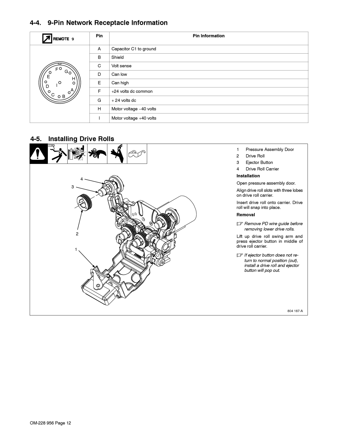
1Pressure Assembly Door
2Drive Roll
3Ejector Button
4Drive Roll Carrier
Installation
Open pressure assembly door.
Align drive roll slots with three lobes on drive roll carrier.
Insert drive roll onto carrier. Drive roll will snap into place.
Removal
.Remove PD wire guide before removing lower drive rolls.
Lift up drive roll swing arm and press ejector button in middle of drive roll carrier.
.If ejector button does not re-
turn to normal position (out), install a drive roll and ejector button will pop out.
804