. Hardware is common and |
| 4 |
|
|
|
not available unless listed. |
| 3 |
|
|
|
|
|
|
| 7 | 8 |
See Table | 2 |
| 6 |
| |
|
| 9 | |||
Drive Roll & Wire Guide Kits |
| 5 |
|
| |
|
|
|
|
|
1 |
| 10 |
|
| 2 |
22 | 12 | 11 |
13 | ||
21 |
|
|
20 |
|
|
| 15 |
|
17 |
| 14 |
18 | 16 |
|
|
| |
19 |
| 804 |
|
|
|
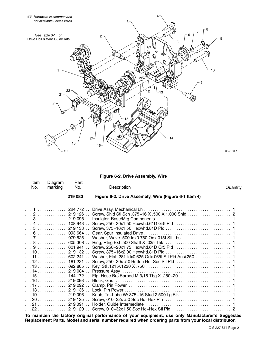
| Figure |
|
| Item | Diagram | Part |
|
|
| No. | marking | No. | Description | Quantity |
|
|
| 219 080 | Figure |
|
|
|
|
|
|
|
. . . | 1 . . . . | . . . . . . . . . | 224 772 . . | Drive Assy, Mechanical Lh | . . . 1 |
. . . | 2 . . . . | . . . . . . . . . | 219 126 . . | Screw, Shld Stl Sch .375−16 X .500 X 1.000 Shld | . . . 2 |
. . . | 3 . . . . | . . . . . . . . . | 219 098 . . | Insulator, Base/Mtg Components | . . . 1 |
. . . | 4 . . . . | . . . . . . . . . | 108 943 . . | Screw, 250−20x1.50 Hexwhd.61D Gr5 Pld | . . . 1 |
. . . | 5 . . . . | . . . . . . . . . | 219 133 . . | Screw, 375−16x1.50 Hexwhd.81D Pld | . . . 1 |
. . . | 6 . . . . | . . . . . . . . . | 093 664 . . | Gear, Spur Insulated Drive | . . . 1 |
. . . | 7 . . . . | . . . . . . . . . | 079 625 . . | Washer, Wave .500 Idx0.750 Odx.015t Stl Lbs | . . . 1 |
. . . | 8 . . . . | . . . . . . . . . | 605 308 . . | Ring, Rtng Ext .500 Shaft X .035 Thk | . . . 1 |
. . . | 9 . . . . | . . . . . . . . . | 601 941 . . | Screw, 250−20x1.75 Hexwhd.61D Gr5 Pld | . . . 1 |
. . . 10 . . . . | . . . . . . . . . | 219 132 . . | Screw, 375−16x2.00 Hexwhd.81D Pld | . . . 1 | |
. . . 11 . . . . | . . . . . . . . . | 602 241 . . | Washer, Flat .281 Idx0.625 Odx.065t Stl Pld Ansi.250 | . . . 1 | |
. . . 12 . . . . | . . . . . . . . . | 181 221 . . | Screw, 250−20x .50 Button Hd−Soc Stl Pld | . . . 1 | |
. . . 13 . . . . | . . . . . . . . . | 092 865 . . | Key, Stl .1215/.1230 X .750 | . . . 1 | |
. . . 14 . . . . | . . . . . . . . . | 219 084 . . | Pressure Assy | . . . 1 | |
. . . 15 . . . . | . . . . . . . . . | 144 172 . . | Ftg, Hose Brs Barbed M 3/16 Tbg X .250−20 | . . . 1 | |
. . . 16 . . . . | . . . . . . . . . | 219 093 . . | Block, Gas | . . . 1 | |
. . . 17 . . . . | . . . . . . . . . | 219 092 . . | Clamp, Pin Power | . . . 1 | |
. . . 18 . . . . | . . . . . . . . . | 219 136 . . | Lock, Pin Power | . . . 1 | |
. . . 19 . . . . | . . . . . . . . . | 219 096 . . | Knob, Tri−Lobe W/.375−16 Stud 2.500 Lg Blk | . . . 1 | |
. . . 20 . . . . | . . . . . . . . . | 219 125 . . | Screw, 010−32x .50 Soc Hd−Hex Pln | . . . 1 | |
. . . 21 . . . . | . . . . . . . . . | 219 091 . . | Holder, Guide Intermediate | . . . 1 | |
. . . 22 . . . . | . . . . . . . . . | 219 129 . . | Screw, 010−32x1.50 Soc Hd−Hex Stl Pld | . . . 2 | |
To maintain the factory original performance of your equipment, use only Manufacturer’s Suggested Replacement Parts. Model and serial number required when ordering parts from your local distributor.
