Item

Dia.


Part

Description


No.


Mkgs.


No.

Quantity


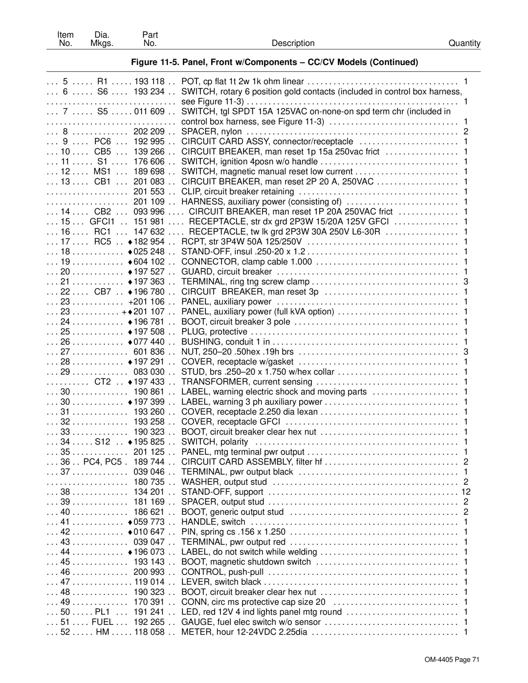
Figure 11-5. Panel, Front w/Components – CC/CV Models (Continued)


. . . 5 . . . . . R1 .

. . .

. 193 118 . .

POT, cp flat 1t 2w 1k ohm linear

. . . 1

. . .

6

. . . . . S6 .

. . .

193 234 . .

SWITCH, rotary 6 position gold contacts (included in control box harness,

. . .

. . .

. .

. . . . . . . .

. . .

. . . . . . . . . . .

see Figure 11-3)

. . . 1

. . .

7

. . . . . S5 .

. . .

. 011 609 . .

SWITCH, tgl SPDT 15A 125VAC on-none-on spd term chr (included in

. . .

. . .

. .

. . . . . . . .

. . .

. . . . . . . . . . .

control box harness, see Figure 11-3)

. . . 1

. . .

8

. .

. . . . . . . .

. . .

202 209 . .

SPACER, nylon

. . . 2

. . .

9

. . . . PC6 . . .

192 995 . .

CIRCUIT CARD ASSY, connector/receptacle

. . . 1

. . . 10

. .

. . CB5 . . .

139 266 . .

CIRCUIT BREAKER, man reset 1p 15a 250vac frict

. . . 1

. . . 11

. .

. . . S1 .

. . .

176 606 . .

SWITCH, ignition 4posn w/o handle

. . . 1

. . . 12

. .

. . MS1 . . .

189 698 . .

SWITCH, magnetic manual reset low current

. . . 1

. . . 13

. .

. . CB1 . . .

201 083 . .

CIRCUIT BREAKER, man reset 2P 20 A, 250VAC

. . . 1

. . .

. . .

. .

. . . . . . . .

. . .

201 553 . .

CLIP, circuit breaker retaining

. . . 1

. . .

. . .

. .

. . . . . . . .

. . .

201 109 . .

HARNESS, auxiliary power (consisting of)

. . . 1

. . . 14

. .

. . CB2 . . .

093 996 . . .

. CIRCUIT BREAKER, man reset 1P 20A 250VAC frict

. . . 1

. . . 15

. .

. GFCI1 . .

151 981 . . .

. RECEPTACLE, str dx grd 2P3W 15/20A 125V GFCI

. . . 1

. . . 16

. .

. . RC1 . . .

147 632 . . .

. RECEPTACLE, tw lk grd 2P3W 30A 250V L6-30R

. . . 1

. . . 17

. .

. . RC5 . .

182 954 . .

RCPT, str 3P4W 50A 125/250V

. . . 1

. . . 18

. .

. . . . . . . .

. .

025 248 . .

STAND-OFF, insul .250-20 x 1.2

. . . 1

. . . 19

. .

. . . . . . . .

. .

604 102 . .

CONNECTOR, clamp cable 1.000

. . . 1

. . . 20

. .

. . . . . . . .

. .

197 527 . .

GUARD, circuit breaker

. . . 1

. . . 21

. .

. . . . . . . .

. .

197 363 . .

TERMINAL, ring tng screw clamp

. . . 3

. . . 22

. .

. . CB7

. .

196 780 . .

CIRCUIT BREAKER, man reset 3p

. . . 1

. . . 23

. .

. . . . . . . .

. . +201 106 . .

PANEL, auxiliary power

. . . 1

. . . 23

. .

. . . . . . . .

. +

201 107 . .

PANEL, auxiliary power (full kVA option)

. . . 1

. . . 24

. .

. . . . . . . .

. .

196 781 . .

BOOT, circuit breaker 3 pole

. . . 1

. . . 25

. .

. . . . . . . .

. .

197 508 . .

PLUG, protective

. . . 1

. . . 26

. .

. . . . . . . .

. .

077 440 . .

BUSHING, conduit 1 in

. . . 1

. . . 27

. .

. . . . . . . .

.. .. .

601 836 . .

NUT, 250–20 .50hex .19h brs

. . . 3

. . . 28

. .

. . . . . . . .

197 291 . .

COVER, receptacle w/gasket

. . . 1

. . . 29

. .

. . . . . . . .

.. .. .

083 030 . .

STUD, brs .250–20 x 1.750 w/hex collar

. . . 1

. . .

. . .

. .

. . CT2

197 433 . .

TRANSFORMER, current sensing

. . . 1

. . . 30

. .

. . . . . . . .

.. .. .

190 861 . .

LABEL, warning electric shock and moving parts

. . . 1

. . . 30

. .

. . . . . . . .

197 399 . .

LABEL, warning 3 ph auxiliary power

. . . 1

. . . 31

. .

. . . . . . . .

. . .

193 260 . .

COVER, receptacle 2.250 dia lexan

. . . 1

. . . 32

. .

. . . . . . . .

. . .

193 258 . .

COVER, receptacle GFCI

. . . 1

. . . 33

. .

. . . . . . . .

.. .. .

190 323 . .

BOOT, circuit breaker clear hex nut

. . . 1

. . . 34

. .

. . . S12

195 825 . .

SWITCH, polarity

. . . 1

. . . 35

. .

. . . . . . . .

. . .

201 125 . .

PANEL, mtg terminal pwr output

. . . 1

. . . 36

. .

PC4, PC5 .

189 744 . .

CIRCUIT CARD ASSEMBLY, filter hf

. . . 2

. . . 37

. .

. . . . . . . .

. . .

039 046 . .

TERMINAL, pwr output black

. . . 1

. . .

. . .

. .

. . . . . . . .

. . .

180 735 . .

WASHER, output stud

. . . 2

. . . 38

. .

. . . . . . . .

. . .

134 201 . .

STAND-OFF, support

. . . 12

. . . 39

. .

. . . . . . . .

. . .

181 169 . .

SPACER, output stud

. . . 2

. . . 40

. .

. . . . . . . .

.. .. .

186 621 . .

BOOT, generic output stud

. . . 2

. . . 41

. .

. . . . . . . .

059 773 . .

HANDLE, switch

. . . 1

. . . 42

. .

. . . . . . . .

. .

010 647 . .

PIN, spring cs .156 x 1.250

. . . 1

. . . 43

. .

. . . . . . . .

.. .. .

039 047 . .

TERMINAL, pwr output red

. . . 1

. . . 44

. .

. . . . . . . .

196 073 . .

LABEL, do not switch while welding

. . . 1

. . . 45

. .

. . . . . . . .

. . .

193 143 . .

BOOT, magnetic shutdown switch

. . . 1

. . . 46

. .

. . . . . . . .

. . .

200 993 . .

CONTROL, push-pull

. . . 1

. . . 47

. .

. . . . . . . .

. . .

. 119 014 . .

LEVER, switch black

. . . 1

. . . 48

. .

. . . . . . . .

. . .

190 323 . .

BOOT, circuit breaker clear hex nut

. . . 1

. . . 49

. .

. . . . . . . .

. . .

170 391 . .

CONN, circ ms protective cap size 20

. . . 1

. . . 50

. .

. . . PL1 . . .

191 241 . .

LED, red 12V 4 ind lights panel mtg round

. . . 1

. . . 51

. .

. . FUEL

. . .

192 265 . .

GAUGE, fuel elec switch w/o sensor

. . . 1

. . . 52

. .

. . . HM .

. . .

. 118 058 . .

METER, hour 12-24VDC 2.25dia

. . . 1

OM-4405 Page 71

Page 75
Image 75
Miller Electric Big 40 WG manual PC6 192

Big 40 WG specifications

The Miller Electric Big 40 WG is a versatile and powerful welding generator designed to meet the demands of professionals in the field. Known for its reliability and robust performance, the Big 40 WG is the ideal choice for those who require both welding capabilities and a portable power source.

One of the standout features of the Big 40 WG is its ability to produce a substantial output of up to 10,000 watts of continuous power. This ensures that users have enough capacity to run various tools and equipment, making it perfect for job sites where electricity may not readily be available. The generator is powered by a Kohler Command PRO engine, renowned for its durability and efficiency, ensuring that users can depend on its performance even in the toughest conditions.

The machine offers a dual capability for electric welding and stick welding, which enables users to tackle a variety of applications, from light maintenance tasks to heavy-duty industrial jobs. The Big 40 WG features an easy-to-use control panel, equipped with clear indicators and outputs that simplify operation. Whether you need to switch between welding modes or adjust settings, the intuitive design allows for quick responses and seamless operation.

In terms of technology and innovation, the Big 40 WG includes advanced features such as an automatic idle speed adjustment, which increases fuel efficiency and reduces wear on the engine. This technology not only helps save on fuel costs but also minimizes noise levels, providing a more pleasant working environment.

Another key characteristic of the Big 40 WG is its portability. Engineered with a lightweight frame and built-in lifting hooks, it is easy to transport and maneuver, making it an excellent choice for on-site work. The rugged construction ensures that the generator can withstand the rigors of outdoor use, enhancing its lifespan and reliability.

For those in search of a welding generator that delivers on performance, functionality, and portability, the Miller Electric Big 40 WG stands out as a preferred option. Its combination of powerful output, advanced technologies, and user-friendly features makes it a valuable tool for professionals across various industries, ensuring they can complete their jobs effectively and efficiently, no matter where they are.