Instructions
Subject to technical changes
Contents of instructions
Updating of documentation
Content
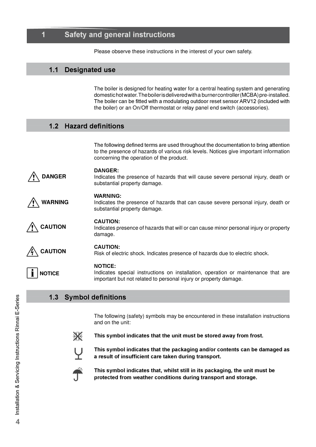
Safety and general instructions
Symbol definitions
Designated use
Hazard definitions
Following instructions must be followed
What to do if YOU Smell GAS
Tools, materials and additional equipment
Follow these instructions for the space heating water
Disposal
Regulations and guidelines
Description of the boiler
Room sealed boiler
Condensing
Modulating
Scope of delivery
Packaging and transportation
Transportation
Installation
Requirements for the installation room
Fitting the boiler
Dimensions
E75CP
Connection for combustion air supply and vent system
Plumbing Kits
Plumbing Kit
Clearances from boiler
Low Loss Header
Technical specifications
CSA
Connecting the boiler
Central heating system
Plumbing Kit installation
Compression fittings
Installation & Servicing Instructions Rinnai E
Safety valve
Low water cut off
Expansion tank
With the boiler
Underfloor heating system plastic pipes
Gas supply connection
Gas connection with natural gas
Gas piping
Gas connection with propane gas
Propane Supply Pressure Requirements
Hot water supply
Condensate drain pipe
Vent system and air supply system
Intake / Exhaust Guidelines
To the boiler. See the list on
Agency
2a Examples vent and air supply systems concentric
2b Examples vent and air supply systems parallel
Installation of the vent system
Concentric system see
Parallel system see
Room Air System outdoor combustion air
Recommended vent/air intake terminal position
Terminal positions
Occur to building products in the vicinity see
Item Description Flue Material United States
Dimensioning of the exhaust and air intake duct
Combustion air and vent piping lengths
Calculation of equivalent length vent system
Parallel system
Total equivalent length Concentric system
Calculation of compensation factor
Boiler type E75 E110
Room Air System indoor combustion air
Unconfined Space
Louvers and Grills
Confined Space
Location
Using Indoor Air For Combustion
Using Outdoor Air For Combustion
Connecting incoming power
Electrical connections
Are used must have a Volt free contact
Connection terminal E-Series
Electrical diagram
Electrical ladder diagram
Boiler controls
Good-state or standard read out
Technical read out
Operation indication
Explanation of the function buttons
Requirements of the water system
Filling the heating system
Freeze protection
With water will have to be done
Do not try to light the burner by hand
Close main gas shut off valve
Adjustments
Altering adjustments
Press the Mode-button for 5 seconds
Press the STORE-button to confirm the code code blinks1
Parameter Mode
Outdoor reset
Boiler and/or the installation
Activating factory settings green button function
Isolating the boiler
Commissioning
Testing the Ignition Safety shut off device
Testing for gas leaks
Start up of the boiler
Type of boiler
Checking for contamination
Boiler needs maintanance
Follow the next procedure
Checking of the zero pressure control
Checking the O2
Installing the casing
Measuring the ionization current
Maintenance
Periodic examination of venting systems and boiler
Inspection
Technician
Checking and adjusting the gas/air ratio
Visual inspection for general signs of corrosion
Measuring the inlet gas pressure
Carrying out a pressure test of the heating system
Maintenance activities
Replace the gasket with a new one
Condensate trap
Condensate tray
Warranty
Visual inspection of the flame
Parts of the boiler
G K
Blocks and Errors
Error indication short reference
Blocks
External safety contact is active
Block
Check flow through the installation
Execute Parameter-Reset
Check flow through the boiler and DHW fascility
Check the sensors NTC 1 and NTC
Check the main Power supply
Check the boiler Pump
Error
Errors
Rectify the short-circuit If necessary replace this part
Check the 24 Volt Connection
Disconnect voltage from the boiler and check the fuse F2
Check Disconnected Components for short-circuiting
Ionisation flow Ionisation cable or O2 setting
Check the data in Error mode
Gas
Reset the boiler
Software error con Trol unit
Rectify the prece Ding error
Error persists After reset Software error Control unit
Software error Control unit
Error
Check the 24 Volt Connections
Remove Voltage from the boiler and check fuse F2
Check Disconnected parts for wear and tear
Software error Control unit
Temperature of 36 is displayed at position
If necessary Replace the flow Sensor
Check actual flow temperature
Check flow sensor NTC1
Check actual return temperature
Check return Sensor NTC
Fuse is working and the error is repeated
Wiring and voltage are OK and error is repeated
Fan is not Spinning
If necessary Replace the fan
Wiring is OK but the error is repeated
Check the wiring
Replace Sensor
Shut down of return sensor T2
Contact for supply sensor T1 open
Check the data Error mode
Software error Control unit
Other errors
Central heating but no hot water
Key of the central heating program is not switched on
Hot water but no central heating
RS100 with outdoor Sensor Room sensor-On
Three-port valve is not circulating to central heating
Key pump program Is on
Insufficient quantity of hot water
Hot and cold water Connection to the boiler Mixed up
Incorrect flow reducing Valve
Absence Positive results
DHW power for the boiler is set too low
Temperature drop of the DHW
Flow reducing valve
Incorrect choice Installation
Radiators do not get hot enough or warming up takes too long
Spare parts
Parts casing E-Series
Installation Manual E-SERIES
Description
Parts heat exchanger E-Series
OSS1 OSS2 Clamp BAR TOP Part H.EX. Long
Parts rear wall E-Series
OSS1 OSS2
Parts pipes E-Series
Description
Parts electrical components E-Series
166 167