2-6. Slope Selection (250 Ampere Model)
4
7
2
6 5
![]() 3
3
1
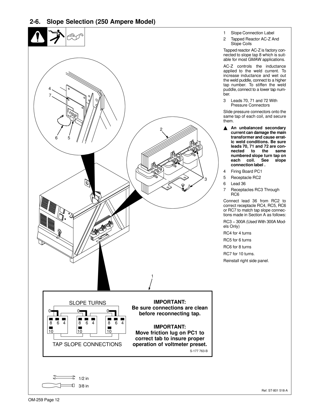
1Slope Connection Label
2Tapped Reactor AC-Z And Slope Coils
Tapped reactor
3Leads 70, 71 and 72 With Pressure Connectors
Slide pressure connectors onto the same tap of each coil, and secure them.
YAn unbalanced secondary current can damage the main transformer and cause errat- ic weld conditions. Be sure leads 70, 71 and 72 are con-
nected to the same numbered slope turn tap on each coil. See slope connection label .
4Firing Board PC1
5Receptacle RC2
6Lead 36
7Receptacles RC3 Through RC6
Connect lead 36 from RC2 to correct receptacle RC4, RC5, RC6 or RC7 to match tap slope connec- tions made in Section A as follows:
RC3 − 300A (Used With 300A Mod- els Only)
RC4 for 4 turns
RC5 for 6 turns
RC6 for 8 turns
RC7 for 10 turns.
Reinstall right side panel.
SLOPE TURNS
0 |
|
|
|
|
|
|
| 0 |
|
|
|
|
|
|
|
| 0 |
|
|
|
|
|
|
|
| |||||
|
|
|
|
|
|
|
|
|
|
|
|
|
|
|
|
|
|
|
|
|
|
| ||||||||
|
|
|
|
|
|
|
|
|
|
|
|
|
|
|
|
|
|
|
|
|
|
| ||||||||
|
|
|
|
|
|
|
|
|
|
|
|
|
|
|
|
|
|
|
|
|
|
|
|
|
|
|
|
|
|
|
|
|
|
|
|
|
|
|
|
|
|
|
|
|
|
|
|
|
|
|
|
|
|
|
|
|
|
| |||
|
|
|
|
|
|
|
|
|
|
|
|
|
|
|
|
|
|
|
|
|
|
|
|
|
|
|
|
| ||
8 |
|
| 6 |
| 4 |
|
| 8 |
|
| 6 | 4 |
|
| 8 |
|
| 6 | 4 |
| ||||||||||
|
|
|
|
|
|
|
|
|
|
|
|
|
|
|
|
|
|
|
|
|
|
|
|
| ||||||
|
|
|
|
|
|
|
|
|
|
|
|
|
|
|
|
|
|
|
|
|
|
|
|
|
|
|
|
|
|
|
10 |
|
|
|
|
|
|
| 10 |
|
|
|
|
|
|
|
| 10 |
|
|
|
|
|
|
| ||||||
|
|
|
|
|
|
|
|
|
|
|
|
|
|
|
|
|
|
|
|
|
|
|
|
|
|
|
|
|
|
|
|
|
|
|
|
|
|
|
|
|
|
|
|
|
|
|
|
|
|
|
|
|
|
|
|
|
|
|
|
|
|
TAP SLOPE CONNECTIONS
IMPORTANT:
Be sure connections are clean
before reconnecting tap.
IMPORTANT:
Move friction lug on PC1 to correct tab to insure proper operation of voltmeter preset.
1/2 in
3/8 in
Ref.
